|
|

|

|
| e-Pub |
Section: New Results
From TIRF microscope calibration to 3D biological reconstructions
Participants : Emmanuel Soubies, Laure Blanc-Féraud, Sébastien Schaub, Gilles Aubert.
This work is made in collaboration with Agata Radwanska, Ellen Van Obberghen-Schilling (iBV).
Total Internal Reflection Fluorescence microscopy (TIRF) is a method of choice to visualize membrane-substrate interactions. The principle of this device relies on the total internal reflection phenomenon generating an evanescent wave capable of producing a selective excitation of the dye molecules within a single layer of 100 to 500nm. The fast decay of the evanescent wave varies with respect to the incident angle of the light beam. Hence, intensity variations on TIRF images, occurring when changing the incident angle, are, in part, due to the axial positions of the observed structures. While a direct interpretation of Multi-Angle TIRF (MA-TIRF) images in terms of axial structure positions is not an easy task, reconstruction algorithms can be dedicated to compute a quantitative depth map with high axial resolution. However, the success of such reconstruction methods strongly depends on the system calibration.
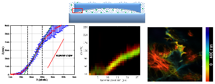
We have proposed a pipeline for MA-TIRF calibration. Considering back focal plane (BFP) images of several solutions differing by their refractive indices, we validate the theoretical relation linking the tension applied to the galvanometric mirror (which controls the laser beam orientation) and the incident angle of the beam on the specimen. Then it is crucial to verify if the simple exponential decaying model of the evanescent wave is sufficient to describe our setup. To this end we propose to build a phantom sample (for which the geometry is known) using a large lens placed into a homogeneous fluorescent solution (Fig. 1 top). Based on a least square estimation, we showed a good agreement between the estimated slope of the lens (we assume the lens to be linear near the border) and the expected one up to 400nm depth (Fig. 1 bottom-left). To complete the validation procedure, we use a sample for which the structures of interest are labeled using two different fluorescent proteins sensitive to different wavelengths and emitting respectively green and red fluorescence. Then, using standard variational approaches, we obtain a co-localization of the reconstructed structures with a precision around 30-40nm (Fig. 1 bottom-middle) over at least 170nm depth showing the precision of the method. Finally, once this calibration step is achieved, we perform color-coded depth representation of 3D biological structures living in the vicinity of the cell membrane (Fig. 1 bottom-right). All these experiments have been made on an experimental TIRF system develloped at iBV lab in Valrose.
|