<?xml version="1.0" encoding="utf-8"?>
<!DOCTYPE html PUBLIC "-//W3C//DTD XHTML 1.1 plus MathML 2.0 plus SVG 1.1//EN" "http://www.w3.org/2002/04/xhtml-math-svg/xhtml-math-svg.dtd">
<html xmlns="http://www.w3.org/1999/xhtml">
  <head>
    <meta http-equiv="Content-Type" content="application/xhtml+xml; charset=utf-8"/>
    <title>Project-Team:APICS</title>
    <link rel="stylesheet" href="../static/css/raweb.css" type="text/css"/>
    <meta name="description" content="Application Domains - Identification and design of microwave devices"/>
    <meta name="dc.title" content="Application Domains - Identification and design of microwave devices"/>
    <meta name="dc.creator" content="Laurent Baratchart"/>
    <meta name="dc.creator" content="Sylvain Chevillard"/>
    <meta name="dc.creator" content="Jean-Paul Marmorat"/>
    <meta name="dc.creator" content="Martine Olivi"/>
    <meta name="dc.creator" content="Fabien Seyfert"/>
    <meta name="dc.subject" content=""/>
    <meta name="dc.publisher" content="INRIA"/>
    <meta name="dc.date" content="(SCHEME=ISO8601) 2016-01"/>
    <meta name="dc.type" content="Report"/>
    <meta name="dc.language" content="(SCHEME=ISO639-1) en"/>
    <meta name="projet" content="APICS"/>
    <script type="text/javascript" src="https://raweb.inria.fr/rapportsactivite/RA2016/static/MathJax/MathJax.js?config=TeX-MML-AM_CHTML">
      <!--MathJax-->
    </script>
  </head>
  <body>
    <div class="tdmdiv">
      <div class="logo">
        <a href="http://www.inria.fr">
          <img style="align:bottom; border:none" src="../static/img/icons/logo_INRIA-coul.jpg" alt="Inria"/>
        </a>
      </div>
      <div class="TdmEntry">
        <div class="tdmentete">
          <a href="uid0.html">Project-Team Apics</a>
        </div>
        <span>
          <a href="uid1.html">Members</a>
        </span>
      </div>
      <div class="TdmEntry">Overall Objectives<ul><li><a href="./uid3.html">Research Themes</a></li></ul></div>
      <div class="TdmEntry">Research Program<ul><li><a href="uid7.html&#10;&#9;&#9;  ">Introduction</a></li><li><a href="uid11.html&#10;&#9;&#9;  ">Range of inverse problems</a></li><li><a href="uid17.html&#10;&#9;&#9;  ">Approximation</a></li><li><a href="uid23.html&#10;&#9;&#9;  ">Software tools of the team</a></li></ul></div>
      <div class="TdmEntry">Application Domains<ul><li><a href="uid46.html&#10;&#9;&#9;  ">Introduction</a></li><li><a href="uid47.html&#10;&#9;&#9;  ">Inverse magnetization problems</a></li><li><a href="uid49.html&#10;&#9;&#9;  ">Inverse source problems in EEG</a></li><li class="tdmActPage"><a href="uid50.html&#10;&#9;&#9;  ">Identification and design of microwave devices</a></li></ul></div>
      <div class="TdmEntry">New Results<ul><li><a href="uid59.html&#10;&#9;&#9;  ">Inverse problems for Poisson-Laplace equations</a></li><li><a href="uid67.html&#10;&#9;&#9;  ">Matching problems and their applications</a></li><li><a href="uid71.html&#10;&#9;&#9;  ">Sensitivities of Electrical Parameters with respect to physical parameters</a></li><li><a href="uid72.html&#10;&#9;&#9;  ">Stability of amplifiers</a></li><li><a href="uid73.html&#10;&#9;&#9;  ">Tools for numerically guaranteed computations</a></li><li><a href="uid74.html&#10;&#9;&#9;  ">Asymptotics of
weighted Bergman polynomials</a></li></ul></div>
      <div class="TdmEntry">Bilateral Contracts and Grants with Industry<ul><li><a href="uid76.html&#10;&#9;&#9;  ">Contract CNES-Inria-XLIM</a></li><li><a href="uid77.html&#10;&#9;&#9;  ">Contract CNES-Inria-UPV/EHU</a></li><li><a href="uid78.html&#10;&#9;&#9;  ">Contract BESA GmbH-Inria</a></li><li><a href="uid80.html&#10;&#9;&#9;  ">Flextronics</a></li></ul></div>
      <div class="TdmEntry">Partnerships and Cooperations<ul><li><a href="uid82.html&#10;&#9;&#9;  ">Regional Initiatives</a></li><li><a href="uid86.html&#10;&#9;&#9;  ">National Initiatives</a></li><li><a href="uid89.html&#10;&#9;&#9;  ">European Initiatives</a></li><li><a href="uid93.html&#10;&#9;&#9;  ">International Initiatives</a></li><li><a href="uid104.html&#10;&#9;&#9;  ">International Research Visitors</a></li><li><a href="uid114.html&#10;&#9;&#9;  ">List of international and industrial partners</a></li></ul></div>
      <div class="TdmEntry">Dissemination<ul><li><a href="uid119.html&#10;&#9;&#9;  ">Promoting Scientific Activities</a></li><li><a href="uid156.html&#10;&#9;&#9;  ">Teaching - Supervision - Juries</a></li><li><a href="uid171.html&#10;&#9;&#9;  ">Popularization</a></li></ul></div>
      <div class="TdmEntry">
        <div>Bibliography</div>
      </div>
      <div class="TdmEntry">
        <ul>
          <li>
            <a id="tdmbibentmajor" href="bibliography.html">Major publications</a>
          </li>
          <li>
            <a id="tdmbibentyear" href="bibliography.html#year">Publications of the year</a>
          </li>
          <li>
            <a id="tdmbibentfoot" href="bibliography.html#References">References in notes</a>
          </li>
        </ul>
      </div>
    </div>
    <div id="main">
      <div class="mainentete">
        <div id="head_agauche">
          <small><a href="http://www.inria.fr">
	    
	    Inria
	  </a> | <a href="../index.html">
	    
	    Raweb 
	    2016</a> | <a href="http://www.inria.fr/en/teams/apics">Presentation of the Project-Team APICS</a> | <a href="http://team.inria.fr/apics/">APICS Web Site
	  </a></small>
        </div>
        <div id="head_adroite">
          <table class="qrcode">
            <tr>
              <td>
                <a href="apics.xml">
                  <img style="align:bottom; border:none" alt="XML" src="../static/img/icons/xml_motif.png"/>
                </a>
              </td>
              <td>
                <a href="apics.pdf">
                  <img style="align:bottom; border:none" alt="PDF" src="IMG/qrcode-apics-pdf.png"/>
                </a>
              </td>
              <td>
                <a href="../apics/apics.epub">
                  <img style="align:bottom; border:none" alt="e-pub" src="IMG/qrcode-apics-epub.png"/>
                </a>
              </td>
            </tr>
            <tr>
              <td/>
              <td>PDF
</td>
              <td>e-Pub
</td>
            </tr>
          </table>
        </div>
      </div>
      <!--FIN du corps du module-->
      <br/>
      <div class="bottomNavigation">
        <div class="tail_aucentre">
          <a href="./uid49.html" accesskey="P"><img style="align:bottom; border:none" alt="previous" src="../static/img/icons/previous_motif.jpg"/> Previous | </a>
          <a href="./uid0.html" accesskey="U"><img style="align:bottom; border:none" alt="up" src="../static/img/icons/up_motif.jpg"/>  Home</a>
          <a href="./uid59.html" accesskey="N"> | Next <img style="align:bottom; border:none" alt="next" src="../static/img/icons/next_motif.jpg"/></a>
        </div>
        <br/>
      </div>
      <div id="textepage">
        <!--DEBUT2 du corps du module-->
        <h2>Section: 
      Application Domains</h2>
        <h3 class="titre3">Identification and design of microwave devices</h3>
        <p class="participants"><span class="part">Participants</span> :
	Laurent Baratchart, Sylvain Chevillard, Jean-Paul Marmorat, Martine Olivi, Fabien Seyfert.</p>
        <p>This is joint work with Stéphane Bila (XLIM, Limoges).</p>
        <p>One of the best training grounds for function-theoretic
applications by the team
is the identification and design of physical systems whose
performance is assessed frequency-wise. This is the case of
electromagnetic resonant systems which are of
common use in
telecommunications.</p>
        <p>In space telecommunications (satellite transmissions),
constraints specific to on-board technology lead to the use of filters
with resonant cavities in the microwave range.
These filters serve multiplexing purposes (before or after
amplification), and consist of a sequence of cylindrical hollow
bodies, magnetically coupled by irises (orthogonal double slits). The
electromagnetic wave that traverses the cavities satisfies the Maxwell
equations, forcing the tangent electrical field along the body of
the cavity to be zero. A deeper study of the Helmholtz
equation states that an essentially discrete set of wave vectors is
selected. In the
considered range of frequency, the electrical field in each cavity can be
decomposed along two orthogonal modes, perpendicular to the axis of the cavity
(other modes are far off in the frequency domain, and their influence can be neglected).
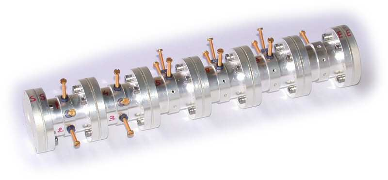
</p>
        <div align="center" style="margin-top:10px">
          <a name="uid51">
            <!--...-->
          </a>
          <table title="" class="objectContainer">
            <caption align="bottom"><strong>Figure
	1. </strong>Picture of a 6-cavities dual mode filter. Each cavity (except the last one) has 3 screws to couple the modes within the
cavity, so that 16 quantities must be optimized. Quantities such as the diameter and length of the cavities, or
the width of the 11 slits are fixed during the design phase.</caption>
            <tr align="center">
              <td>
                <table>
                  <tr>
                    <td style="height:3px;" align="center">
                      <img style="width:427.0pt" alt="IMG/bibande11p4z.png" src="IMG/bibande11p4z.png"/>
                    </td>
                  </tr>
                </table>
              </td>
            </tr>
          </table>
        </div>
        <p>Each cavity (see Figure <a title="Identification and design of microwave devices" href="./uid50.html#uid51">1</a>) has three screws, horizontal, vertical and
midway (horizontal and vertical are two arbitrary directions, the third
direction makes an angle of 45 or 135 degrees, the easy case is when all
cavities show the same orientation, and when the directions of the irises are
the same, as well as the input and output slits). Since screws are
conductors, they behave as capacitors; besides, the
electrical field on the surface has to be zero, which modifies the boundary conditions
of one of the two modes (for the other mode, the electrical field is zero
hence it is not influenced by the screw), the third screw acts as a coupling
between the two modes. The effect of an iris is opposite to that of a
screw: no condition is imposed on a hole, which results in a
coupling between two horizontal (or two vertical) modes of adjacent cavities
(in fact the iris is the union of two rectangles, the important parameter
being their width). The design of a filter consists in finding the size
of each cavity, and the width of each iris. Subsequently, the filter can be
constructed and tuned by adjusting the screws. Finally, the screws are glued
once a satisfactory response has been obtained.
In what follows, we shall consider a typical example, a filter designed by the
CNES in Toulouse, with four cavities near 11 GHz.</p>
        <p>Near the resonance frequency, a good approximation to the Helmholtz
equations is
given by a second order differential equation. Thus,
one obtains
an electrical model of the filter as a sequence of electrically-coupled
resonant circuits, each circuit being modeled by two resonators, one
per mode, the resonance frequency of which represents
the frequency of a mode, and
whose resistance accounts for electric losses (surface currents) in
the cavities.</p>
        <p>This way, the filter can be seen as a quadripole, with two ports, when
plugged onto a resistor at one end and fed with some potential at the other end.
One is now
interested in the power which is transmitted and reflected. This leads
one to define a
scattering matrix <span class="math"><math xmlns="http://www.w3.org/1998/Math/MathML"><mi>S</mi></math></span>, which may be considered as the transfer function of a
stable causal linear dynamical system, with two inputs and two outputs. Its
diagonal terms <span class="math"><math xmlns="http://www.w3.org/1998/Math/MathML"><msub><mi>S</mi><mrow><mn>1</mn><mo>,</mo><mn>1</mn></mrow></msub></math></span>, <span class="math"><math xmlns="http://www.w3.org/1998/Math/MathML"><msub><mi>S</mi><mrow><mn>2</mn><mo>,</mo><mn>2</mn></mrow></msub></math></span> correspond to reflections at each port,
while
<span class="math"><math xmlns="http://www.w3.org/1998/Math/MathML"><msub><mi>S</mi><mrow><mn>1</mn><mo>,</mo><mn>2</mn></mrow></msub></math></span>, <span class="math"><math xmlns="http://www.w3.org/1998/Math/MathML"><msub><mi>S</mi><mrow><mn>2</mn><mo>,</mo><mn>1</mn></mrow></msub></math></span> correspond to transmission. These functions can be
measured at certain frequencies (on the imaginary axis).
The matrix <span class="math"><math xmlns="http://www.w3.org/1998/Math/MathML"><mi>S</mi></math></span> is approximately
rational of order 4 times the number of cavities
(that is 16 in the
example on Figure <a title="Identification and design of microwave devices" href="./uid50.html#uid57">2</a>), and the key step consists in expressing the components of the
equivalent electrical circuit as functions of the <span class="math"><math xmlns="http://www.w3.org/1998/Math/MathML"><msub><mi>S</mi><mrow><mi>i</mi><mi>j</mi></mrow></msub></math></span> (since there are no
formulas expressing the lengths of the screws in terms of parameters of this
electrical model). This representation is also useful
to analyze the numerical simulations of the Maxwell equations, and
to check the quality of a design, in particular the
absence of higher resonant modes.</p>
        <p>In fact, resonance is not studied via the electrical model,
but via a low-pass
equivalent circuit obtained upon linearizing near the central frequency, which is no
longer
conjugate symmetric (<i>i.e.</i> the underlying system may no longer
have real
coefficients) but whose degree is divided by 2 (8 in the example).</p>
        <p>In short, the strategy for identification is as follows:</p>
        <ul>
          <li>
            <p class="notaparagraph"><a name="uid52"> </a>measuring the scattering matrix of the filter near the
optimal frequency over twice the pass band
(which is 80MHz in the example).</p>
          </li>
          <li>
            <p class="notaparagraph"><a name="uid53"> </a>Solving bounded extremal problems for the transmission
and the reflection (the modulus of he response
being respectively
close to 0 and 1 outside the interval measurement, cf. Section <a title="Approximation" href="./uid17.html#uid18">3.3.1</a>) in order to get a models for the scattering matrix as an analytic matrix-valued function.
This provides us with a scattering matrix known to be close
to a rational matrix of order roughly 1/4 of the number of
data points.</p>
          </li>
          <li>
            <p class="notaparagraph"><a name="uid54"> </a>Approximating this scattering matrix by a true rational transfer-function
of appropriate degree
(8 in this example)
via the Endymion or RARL2 software (cf. Section <a title="Approximation" href="./uid17.html#uid21">3.3.2.2</a>).</p>
          </li>
          <li>
            <p class="notaparagraph"><a name="uid55"> </a>A state space realization of <span class="math"><math xmlns="http://www.w3.org/1998/Math/MathML"><mi>S</mi></math></span>, viewed as
a transfer function, can then be obtained, where
additional symmetry constraints coming from the reciprocity law and
possibly other physical features of the device have to be imposed.</p>
          </li>
          <li>
            <p class="notaparagraph"><a name="uid56"> </a>Finally one builds a realization of the approximant
and looks for a
change of variables that eliminates non-physical couplings.
This is obtained by
using algebraic-solvers and continuation
algorithms on the group of orthogonal complex matrices (symmetry
forces this type of transformation).</p>
          </li>
        </ul>
        <div align="center" style="margin-top:10px">
          <a name="uid57">
            <!--...-->
          </a>
          <table title="" class="objectContainer">
            <caption align="bottom"><strong>Figure
	2. </strong>Nyquist Diagram. Rational approximation (degree 8) and data - <span class="math"><math xmlns="http://www.w3.org/1998/Math/MathML"><msub><mi>S</mi><mn>22</mn></msub></math></span>.</caption>
            <tr align="center">
              <td>
                <table>
                  <tr>
                    <td style="height:3px;" align="center">
                      <img style="width:199.16928pt" alt="IMG/nappratS22.png" src="IMG/nappratS22.png"/>
                    </td>
                  </tr>
                </table>
              </td>
            </tr>
          </table>
        </div>
        <p>
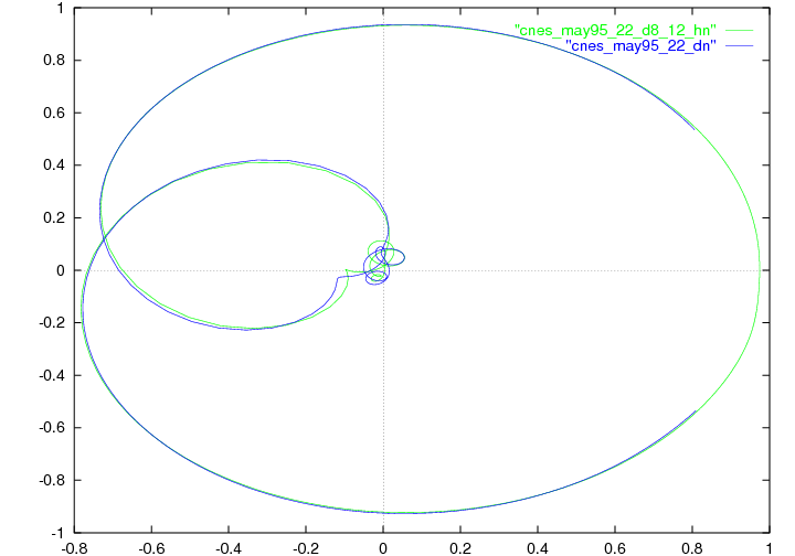
The final approximation is of high quality. This can be interpreted as
a confirmation of the linearity assumption on the system:
the relative <span class="math"><math xmlns="http://www.w3.org/1998/Math/MathML"><msup><mi>L</mi><mn>2</mn></msup></math></span> error is less than <span class="math"><math xmlns="http://www.w3.org/1998/Math/MathML"><msup><mn>10</mn><mrow><mo>-</mo><mn>3</mn></mrow></msup></math></span>.
This is illustrated by a reflection diagram
(Figure <a title="Identification and design of microwave devices" href="./uid50.html#uid57">2</a>). Non-physical couplings are less than <span class="math"><math xmlns="http://www.w3.org/1998/Math/MathML"><msup><mn>10</mn><mrow><mo>-</mo><mn>2</mn></mrow></msup></math></span>.</p>
        <p>The above considerations are valid for a large class of filters. These
developments have also been used for the design of non-symmetric filters,
which are useful for the synthesis of repeating devices.</p>
        <p>The team further investigates problems relative to the design of optimal responses for microwave devices. The resolution of a quasi-convex Zolotarev problems was proposed, in order to derive guaranteed optimal multi-band filter responses subject to modulus constraints <a href="./bibliography.html#apics-2016-bid30">[8]</a>. This generalizes the classical single band design techniques based on Chebyshev polynomials and elliptic functions. The approach relies on the fact that the modulus of the scattering parameter <span class="math"><math xmlns="http://www.w3.org/1998/Math/MathML"><mrow><mrow><mo>|</mo></mrow><msub><mi>S</mi><mrow><mn>1</mn><mo>,</mo><mn>2</mn></mrow></msub><mrow><mo>|</mo></mrow></mrow></math></span> admits a simple expression in terms of the filtering function <span class="math"><math xmlns="http://www.w3.org/1998/Math/MathML"><mrow><mrow><mi>D</mi><mo>=</mo><mo>|</mo></mrow><msub><mi>S</mi><mrow><mn>1</mn><mo>,</mo><mn>1</mn></mrow></msub><mrow><mo>|</mo><mo>/</mo><mo>|</mo></mrow><msub><mi>S</mi><mrow><mn>1</mn><mo>,</mo><mn>2</mn></mrow></msub><mrow><mo>|</mo></mrow></mrow></math></span>, namely</p>
        <div align="center" class="mathdisplay">
          <math xmlns="http://www.w3.org/1998/Math/MathML">
            <mrow>
              <mrow>
                <mo>|</mo>
              </mrow>
              <msub>
                <mi>S</mi>
                <mrow>
                  <mn>1</mn>
                  <mo>,</mo>
                  <mn>2</mn>
                </mrow>
              </msub>
              <msup>
                <mrow>
                  <mo>|</mo>
                </mrow>
                <mn>2</mn>
              </msup>
              <mo>=</mo>
              <mfrac>
                <mn>1</mn>
                <mrow>
                  <mn>1</mn>
                  <mo>+</mo>
                  <msup>
                    <mi>D</mi>
                    <mn>2</mn>
                  </msup>
                </mrow>
              </mfrac>
              <mo>.</mo>
            </mrow>
          </math>
        </div>
        <p class="notaparagraph">The filtering function appears to be the ratio of two polynomials <span class="math"><math xmlns="http://www.w3.org/1998/Math/MathML"><mrow><msub><mi>p</mi><mn>1</mn></msub><mo>/</mo><msub><mi>p</mi><mn>2</mn></msub></mrow></math></span>, the numerator of the reflection and transmission scattering factors, that may be chosen freely. The denominator <span class="math"><math xmlns="http://www.w3.org/1998/Math/MathML"><mi>q</mi></math></span> is then obtained as the unique stable unitary polynomial solving the classical Feldtkeller spectral equation:</p>
        <div align="center" class="mathdisplay">
          <math xmlns="http://www.w3.org/1998/Math/MathML">
            <mrow>
              <mi>q</mi>
              <msup>
                <mi>q</mi>
                <mo>*</mo>
              </msup>
              <mo>=</mo>
              <msub>
                <mi>p</mi>
                <mn>1</mn>
              </msub>
              <msubsup>
                <mi>p</mi>
                <mn>1</mn>
                <mo>*</mo>
              </msubsup>
              <mo>+</mo>
              <msub>
                <mi>p</mi>
                <mn>2</mn>
              </msub>
              <msubsup>
                <mi>p</mi>
                <mn>2</mn>
                <mo>*</mo>
              </msubsup>
              <mo>.</mo>
            </mrow>
          </math>
        </div>
        <p>The relative simplicity of the derivation of a filter's response, under
modulus constraints, owes much to the possibility of
forgetting about Feldtkeller's equation and express all design constraints
in terms of the filtering function. This no longer the case when
considering the synthesis <span class="math"><math xmlns="http://www.w3.org/1998/Math/MathML"><mi>N</mi></math></span>-port devices for <span class="math"><math xmlns="http://www.w3.org/1998/Math/MathML"><mrow><mi>N</mi><mo>&gt;</mo><mn>3</mn></mrow></math></span>, like multiplexers,
routers and power dividers, or when considering the synthesis of filters under
matching conditions. The efficient derivation of multiplexers responses is
the subject of recent investigation by Apics, using techniques based on
constrained Nevanlinna-Pick interpolation
(see Section <a title="Matching problems and their applications" href="./uid67.html">5.2</a>).</p>
        <p>Through contacts with CNES (Toulouse) and UPV (Bilbao),
Apics got additionally involved
in the design of amplifiers which, unlike filters, are active devices.
A prominent issue here is stability. A twenty years back, it was not
possible to simulate unstable responses, and only after building a device
could one detect instability. The advent of so-called <i>harmonic balance</i>
techniques, which compute steady state responses of linear elements in
the frequency domain and look for a periodic state in the time domain of
a network connecting these linear elements <i>via</i>
static non-linearities made it possible to compute the harmonic response
of a (possibly nonlinear and unstable) device <a href="./bibliography.html#apics-2016-bid65">[78]</a>.
This has had tremendous impact on
design, and there is a growing demand for software analyzers.
The team is also becoming active in this area.</p>
        <p>In this connection, there are two types of stability involved. The first is stability of a fixed
point around which the linearized transfer function
accounts for small signal amplification. The second is stability of a
limit cycle which is reached when the input signal is no longer small
and truly nonlinear amplification is attained
(<i>e.g.</i> because of saturation).
Work by the team so far has been concerned with the first type of stability,
and emphasis is put on defining and extracting the “unstable part” of the response, see Section <a title="Stability of amplifiers" href="./uid72.html">5.4</a>. The stability check for
limit cycles is now under investigation.
</p>
      </div>
      <!--FIN du corps du module-->
      <br/>
      <div class="bottomNavigation">
        <div class="tail_aucentre">
          <a href="./uid49.html" accesskey="P"><img style="align:bottom; border:none" alt="previous" src="../static/img/icons/previous_motif.jpg"/> Previous | </a>
          <a href="./uid0.html" accesskey="U"><img style="align:bottom; border:none" alt="up" src="../static/img/icons/up_motif.jpg"/>  Home</a>
          <a href="./uid59.html" accesskey="N"> | Next <img style="align:bottom; border:none" alt="next" src="../static/img/icons/next_motif.jpg"/></a>
        </div>
        <br/>
      </div>
    </div>
  </body>
</html>
