Section:
New Results
Incompressible flow schemes on octrees.
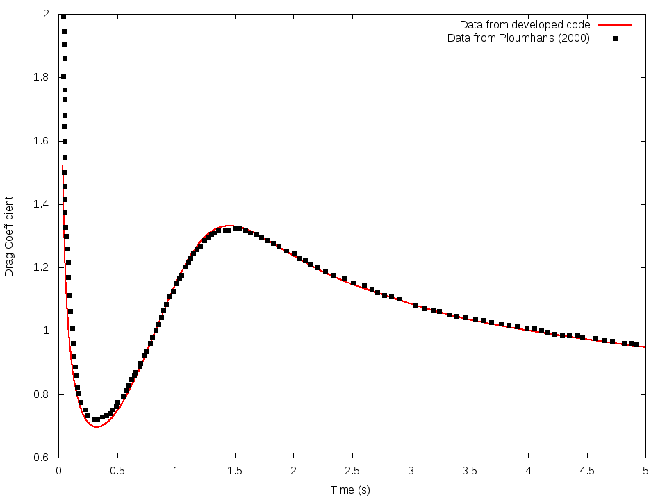
The incompressible Navier-Stokes solver was validated in 2D last years thanks to the computation of the order of convergence. This year, a comparison has been done with data from literature. A first test-case was the flow around a 2-D cylinder. On the figure 9 can be seen a comparison between results from the developed solver and data from literature [Ploumhans (2000)].
Figure
9. Comparison of drag coefficients between the code developped and data from literature for the flow around a cylinder at
|
|
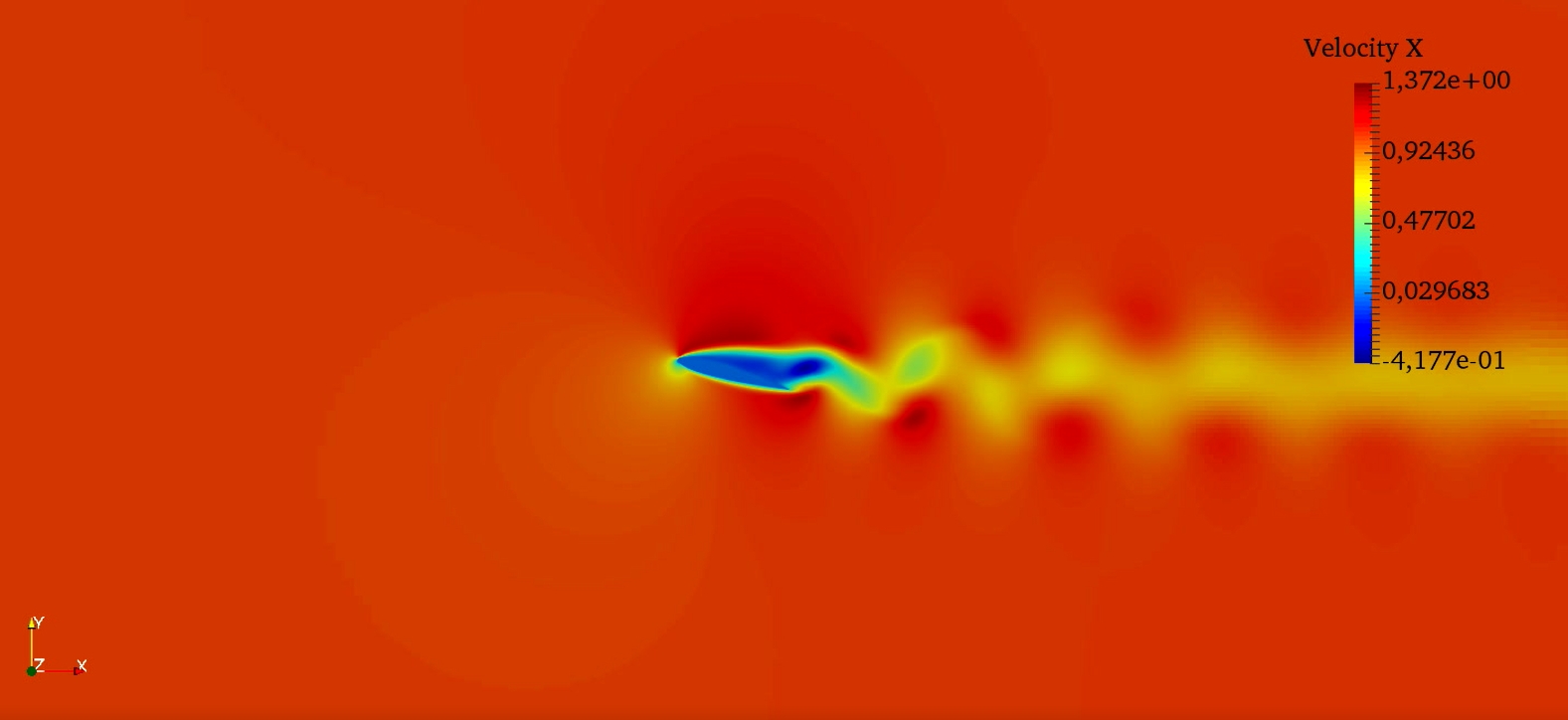
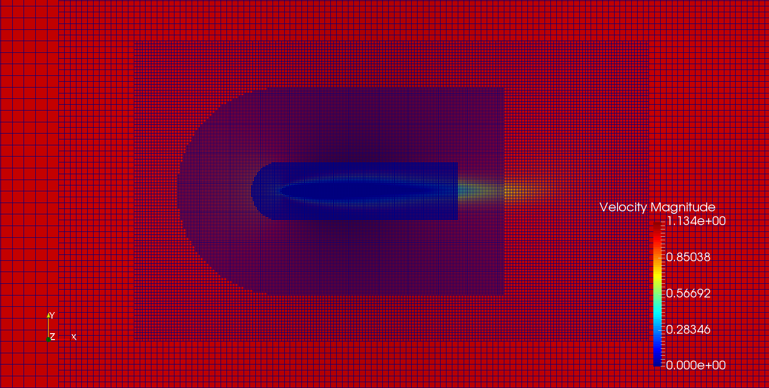
A second test case was the flow around a Naca0012 airfoil. The figure 10 shows the X-Velocity around the airfoil at Re = 1000 with an angle of attack of 15°. A QuadTree grid has been used as can be seen in figure 11. The aerodynamic coeficients have been computed for this test-case and have been compared with data from literature [D. F. Kurtulus (2015)]. With and the results are in good agreement with and from literature data gathered in [D. F. Kurtulus (2015)].
Figure
10. X-Velocity around a Naca0012 airfoil at with an angle of attack of 15°
|
|
Figure
11. QuadTree grid around a Naca0012 airfoil
|
|
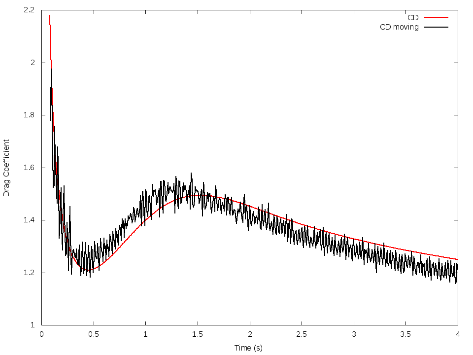
Then, a grid adaptation process has been developed. It allows for exemple to deal with moving bodies and to focus on interesting areas in the computational domain. With user defined criteria, the grid is indeed automatically refined or coarsened. So, this code allows a fast meshing of the computational domain thanks to the penalization approach. An interesting compromise between computational time and accuracy is also reached thanks to the adaptive mesh refinement process. A validation of the adaptive mesh refinement process has been done with a comparison between 2 cases : the case of the flow around a fixed body with an inflow of 1 and the case of a moving body with a velocity of 1 in a fixed flow. It can be seen on figure 12.
Figure
12. Comparison with drag coeficient obtained with a fixed body in a flow and with a moving body with a velocity of in a fixed flow
|
|
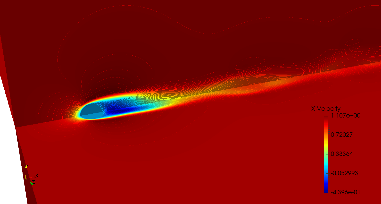
An extension of the code to 3-D has been developed and validated. Again, 2 different test-cases has been chosen for the validation. First, the flow around a sphere has been computed at different Reynolds number and a comparison has been done with several data from literature as shown in table 1. The figure 13 shows the X-Velocity of the flow around a sphere at with Octree grid.
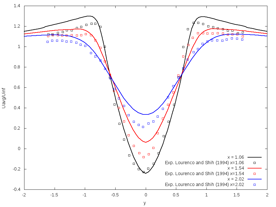
A LES turbulence model has been implemented with a Vreman subgrid model. So, the second test-case is the flow around a cylinder at with LES. The wake profile at different positions has been compared with experimental data as can be seen in figure 14.
Table
1. Comparison of drag coefficients with data from literature at different Reynolds Number
| Re |
Present work |
[Campregher (2009)] |
[Fornberg (1988)] |
[Fadlun et al. (2000)] |
[Kim et al. (2001)] |
[Subramanian (2003)] |
| 300 |
0.6268 |
0.675 |
- |
- |
0.657 |
0.653 |
| 500 |
0.5488 |
0.52 |
0.4818 |
0.476 |
- |
0.555 |
Figure
13. X-Velocity around a sphere at
|
|
Figure
14. Wake profile at different positions behind a cylinder at obtained by averaging Velocity after a preliminary simulation
|
|
As the overall aim is to simulate the aeroelastic effects on a wind turbine subjected to gusts, a dynamic beam model with axial, torsional and flexural deformations have been implemented and coupled wih the Octree Navier-Stokes solver.