Section: New Results
Perception and Situation Awareness in Dynamic Environments
Sensor Fusion for state parameters identification
Participants : Agostino Martinelli, Chiara Troiani.
Problem adressed and background
The general framework based on the new concept of continuous symmetry developed during the last two years (see [67] for a detailed description of this framework) has been extensively applied to investigate the visual inertial structure from motion problem. This problem was already considered in 2011. During 2012 more general results have been found. Special attention has been devoted to identify the conditions under which the problem has a finite number of solutions. Specifically, it has been shown that the problem can have a unique solution, two distinct solutions and infinite solutions depending on the trajectory, on the number of point-features and on their layout and on the number of camera images. The investigation has also performed in the case when the inertial data are biased, showing that, in this latter case, more images and more restrictive conditions on the trajectory are required for the problem resolvability.
Theorical results
The new results have been published on the journal of Transaction on Robotics [68] , in a technical report [43] and submitted to the International Journal of Computer Vision. We have also considered the case of structured light. Specifically, we have considered a sensor assembling (from now on aerial vehicle) consisting of a monocular camera and inertial sensors. Additionally, a laser pointer is mounted on the aerial vehicle and it produces a laser spot. The laser spot is observed by the monocular camera and it is the unique point feature used in the proposed approach. We focus our attention to the case when the aerial vehicle moves in proximity of a planar surface and in particular when the laser spot belongs to this surface. We introduced two novel contributions. The former is the analytical derivation of all the observable modes, i.e., all the physical quantities that can be determined by only using the inertial data and the camera observations of the laser spot during a short time-interval. This derivation was based on the framework introduced in [67] . Specifically, it is shown that the observable modes are: the distance of the vehicle from the planar surface; the component of the vehicle speed, which is orthogonal to the planar surface; the relative orientation of the vehicle with respect to the planar surface; the orientation of the planar surface with respect to the gravity. The second contribution is the introduction of a simple recursive method to perform the estimation of all the aforementioned observable modes. This method is based on a local decomposition of the original system, which separates the observable modes from the rest of the system. The method has been validated by using synthetic data. Additionally, preliminary tests with real data are provided and more complete experiments are in progress. The presented approach can be integrated in the framework of autonomous take-off and landing, safe touch-down and low altitude manoeuvres even in dark or featureless environment. These results have been published in the iros conference [31]
Experimental results
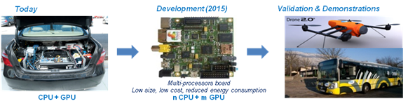
In parallel to this theoretical activity an experimental activity has been carried out in order to deploy our technologies to industrial partners. To this regard, we had a collaboration with the company Delta Drone in Grenoble. In this framework we introduced a new method to localize a micro aerial vehicle (MAV) in GPS denied environments and without the usage of any known pattern. The method exploits the planar ground assumption and only uses the data provided by a monocular camera and an inertial measurement unit. It is based on a closed solution which provides the vehicle pose from a single camera image, once the roll and the pitch angles are obtained by the inertial measurements. Specifically, the vehicle position and attitude can uniquely be determined by having two point features. However, the precision is significantly improved by using three point features. The closed form solution makes the method very simple in terms of computational cost and therefore very suitable for real time implementation. Additionally, because of this closed solution, the method does not need any initialization. We have implemented this method on the platform available in our lab. This is a Pelican from Ascending Technologies equipped with an Intel Atom processor board (1.6 GHz, 1 GB RAM) (figure 1 ).
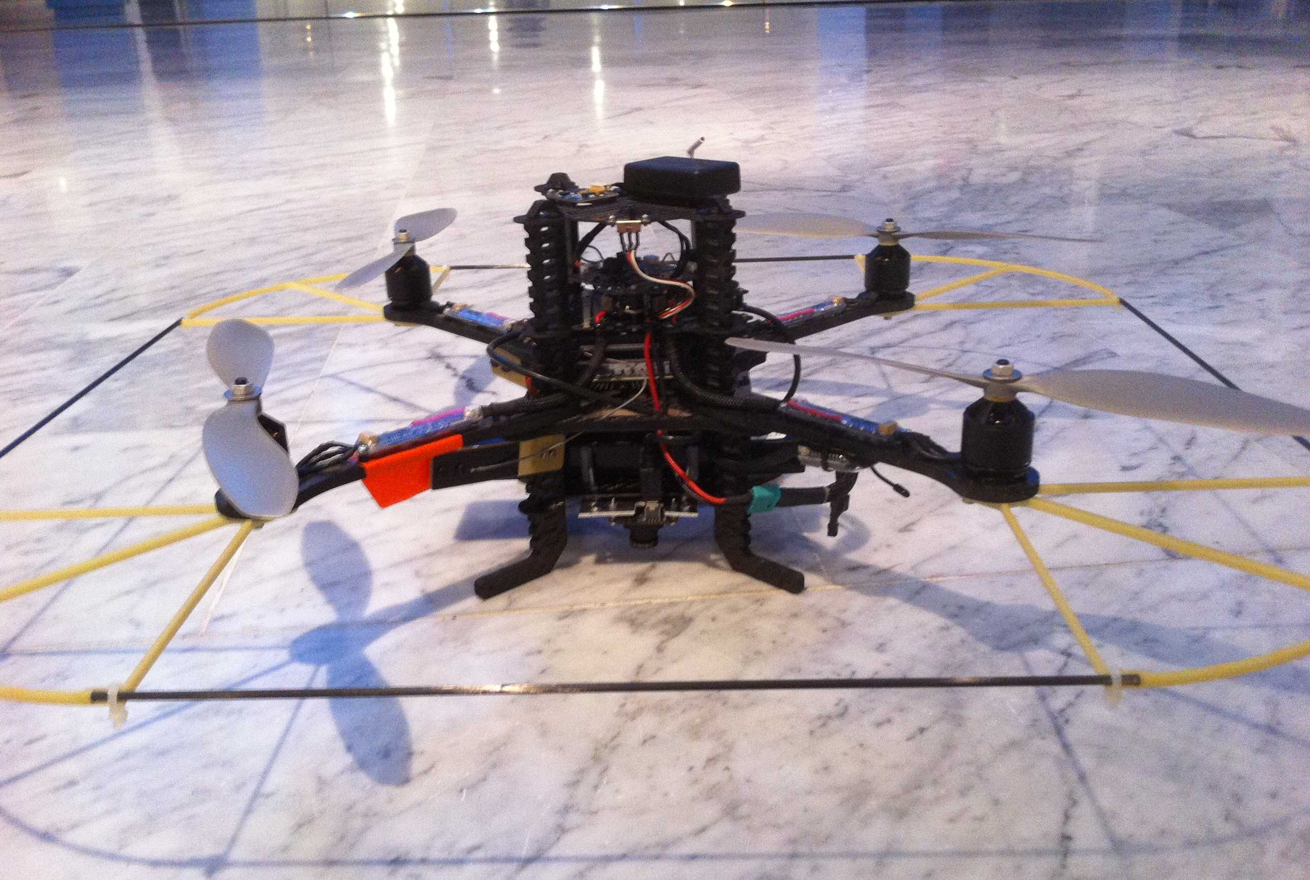
Our sensor suite consists of an Inertial Measurement Unit (3-Axis Gyro, 3-Axis Accelerometer) belonging to the Flight Control Unit (FCU) “AscTec Autopilot” , and a monocular camera (Matrix Vision mvBlueFOX, : ). The camera is calibrated using the Camera Calibration Toolbox for Matlab by J.Y. Bouguet at caltech. The calibration between IMU and camera has been performed using the Inertial Measurement Unit and Camera Calibration Toolbox in [66] . The IMU provides measurements update at a rate of , while the camera framerate is . The Low Level Processor (LLP) of our Pelican is flashed with the 2012 LLP Firmware and performs attitude data fusion and attitude control. We flashed the High Level Processor (HLP) with the asctec_hl_firmware [48] . The onboard computer runs linux 10.04 and ROS (Robot Operating System). We implemented our method using ROS as a middleware for communication and monitoring . The HLP communicates with the onboard computer through a FCU-ROS node. The communication between the camera and the onboard computer is achieved by a ROS node as well. The presented algorithms are running online and onboard at .
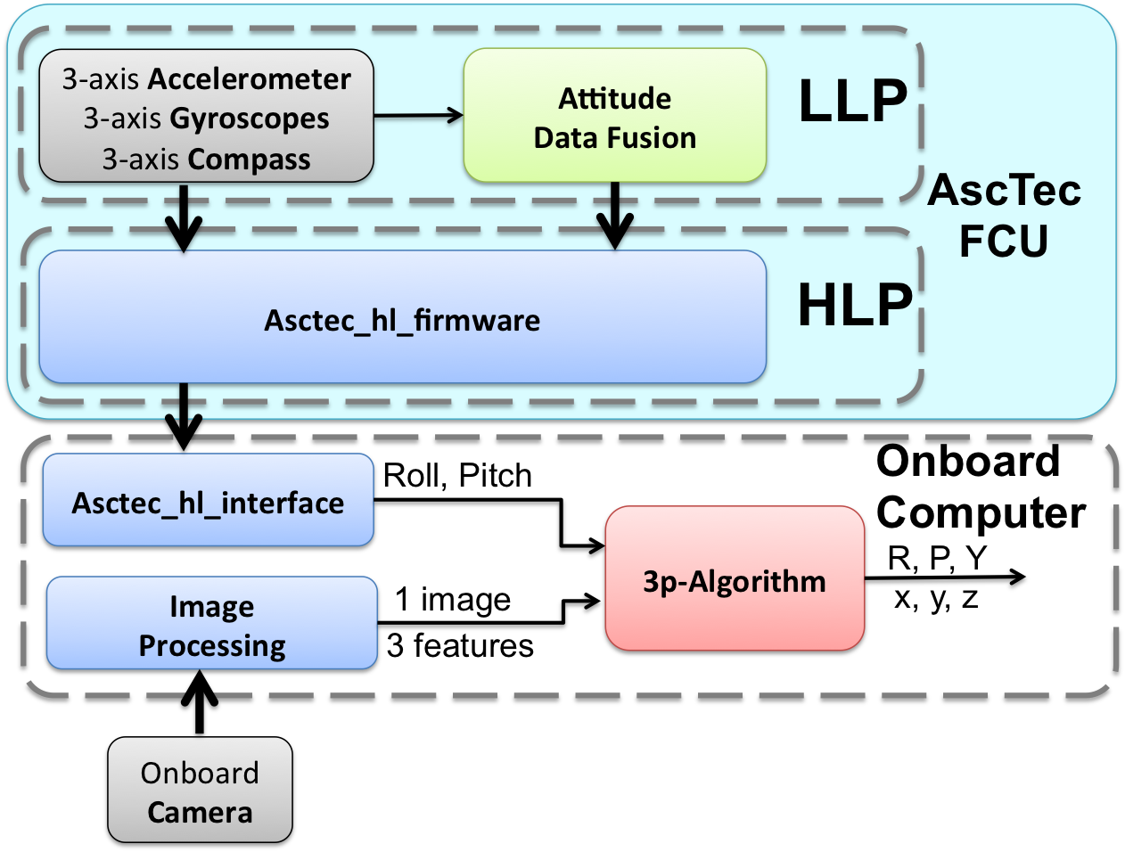
The scenario setup is shown in figure 3 . Since our lab is not yet equipped with a Motion Capture System, we used an ARToolKit Marker with the only aim of having a ground truth to evaluate the performance of our approach. The estimation of the camera pose provided by the marker is not used to perform the estimation. The marker is positioned such that it's reference frame is coincident with the configuration shown in figure 3 . The three features considered are the center of the three little balls in figure 3 . The use of three blob markers instead of natural features is only related to the need to get a ground truth. The information related to the pattern composed by the 3 features (, , ) is only used to evaluate the performance of our approach. The algorithm does not require any information about the features configuration.
|
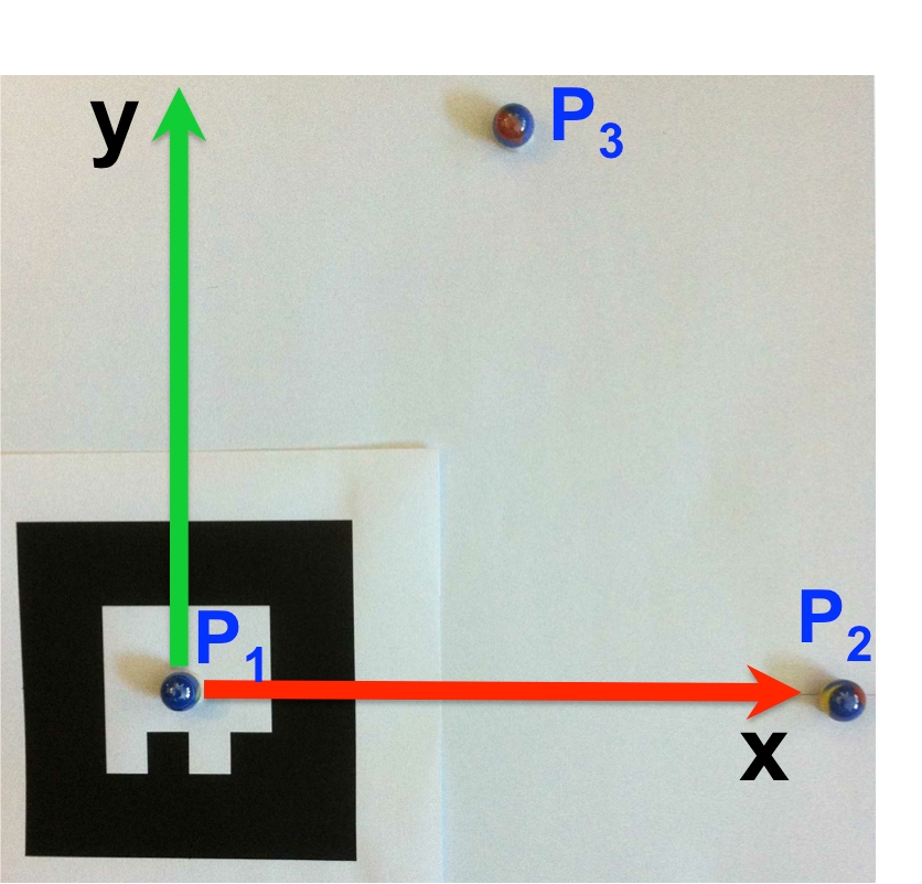
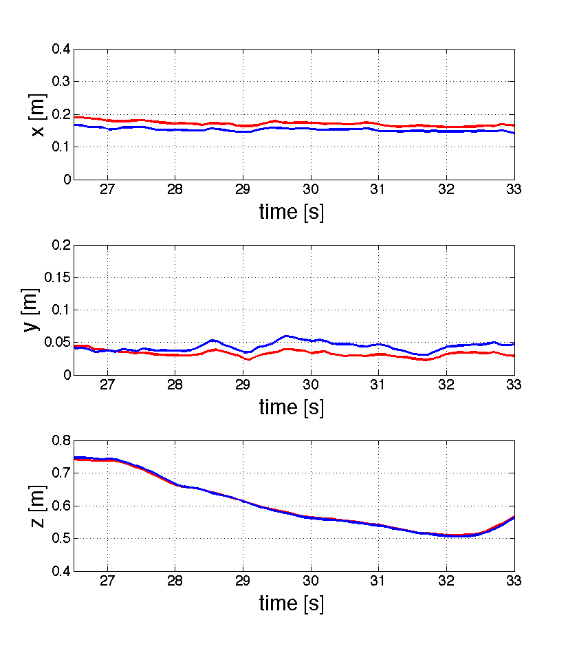
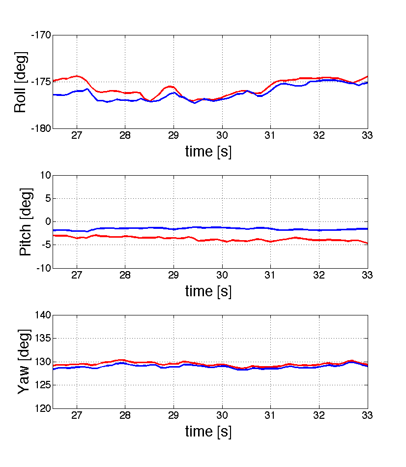
Figure 4 and 5 show respectively the position and the attitude by using the proposed approach. The estimated values are compared with the ground truth obtained with the ARToolkit marker. From figure 4 we see that the difference between our estimates and the ground truth values is of the order of for and and less than for z. From figure 5 we see that the difference between our estimates and the ground truth values is of the order of for and less than for and .
|
|
We believe that the main source of error is due to the distortion of the lens, which is not fully compensated by the calibration. Note that this distortion also affects our ground truth. We plan to test our approach in an environment equipped with a Motion Capture System.
This method is currently under evaluation to be patented.
Visual recognition for intelligent vehicles
Participants : Alexandros Makris, Mathias Perrollaz, Christian Laugier.
We developed a generic object class recognition method. The state-of-the-art visual object class recognition systems operate with local descriptors and codebook representation of the objects. Various local features (e.g., gradient maps, edges) are used to create the descriptors. Then kernel based classifiers are commonly employed to classify the detected features in one of several object classes [50] [54] . The recognition of vehicles or pedestrians from sensors mounted on a moving platform is achieved by different approaches using various types of sensors, e.g., stereo camera, laser [61] [52] . The approaches that perform data fusion from various sensors have proven to be the more robust in a variety of road conditions [76] .
Our work focuses on the development of an object class recognition system which follows the part based detection approach [65] . The system fuses intensity and depth information in a probabilistic framework. To train the system for a specific object class, a database of annotated with bounding boxes images of the class objects is required. Therefore, extending the system to recognize different object classes is straightforward. We apply our method to the problem of detecting vehicles by means of on-board sensors. Initially, depth information is used to find regions of interest. Additionally, the depth of each local feature is used to weight its contribution to the posterior of the object position in the corresponding scale. The votes are then accumulated in a 3d space-scale space and the possible detections are the local maxima in that space.
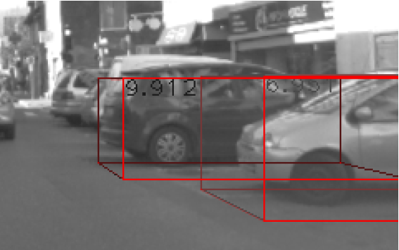
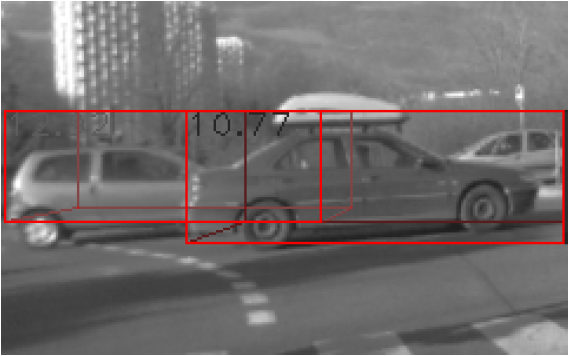
The novelty of our approach is the fusion of depth and intensity information to form a probabilistic part-based detector. Using depth information is beneficial for the robustness of the approach, because we avoid including many noisy detections resulting from false matches between features of different scales. The method is tested with stereo video sequences captured in an urban environment. Figure 6 shows some example detections. The proposed method detects cars in various scales, in cases with partial occlusions, and under significant background clutter.
|
In 2012, we worked on two particular improvements of the method. First, we modified the weighting strategy in order to increase the detection of partially occulded objects. This approach effectively improves the detection results. Second, we consider replacing the current depth descriptor, which only integrates depth information, with a more advanced depth descriptor (e.g., the NARF descriptor). This work is still in progress, in collaboration with Dimitrios Kanoulas, PhD student in Northeastern University (USA).
In 2012, the full method for objects recognition has been submitted for publication in IEEE Transactions on Intelligent Transportation Systems.
Bayesian Motion Detection in Dynamic Environments
Participants : Qadeer Baig, Jander Perrollaz, Mathias Botelho, Christian Laugier.
Introduction
Bayesian Occupancy Filter (BOF) [51] is a grid based perception framework that we use for environment monitoring. In this representation this framework estimates the probability of occupancy as well as velocity of each cell of this grid using sensor data. Output of this framework is used by Fast Clustering Tracking Algorithm (FCTA) [69] to cluster objects and to track them. An important point is that BOF estimates cell velocities without motion information of the ego vehicle, so these are relative velocities. Since no motion information are used, the static objects observed from the moving ego vehicle are also tracked, this results into many false moving objects. Although many of these false positives can be removed by tuning parameters of FCTA, however, this usually is a time consuming task. We note that the number of false can be reduced as well as dependence on FCTA parameters can be relaxed if we can separate the input to BOF into static and dynamic parts. Adding these motion information with cells will allow BOF to calculate velocity information for moving cells only and FCTA will also ignore the static cells while clustering step resulting into faster calculations and better track. In this context we have developed a very fast motion detection technique to separate BOF input into static and dynamic parts. The integration of this module with BOF and FCTA has helped us remove about 78% of the false positives. This technique is summarized next.
Fast Motion Detection
In this section we summarize the technique that we have developed to find moving parts of the environment. This motion detection module is situated in the processing chain just before the BOF. The input to this module consists of an occupancy grid generated by the fusion module. And the output of this module is used by both BOF and FCTA modules.
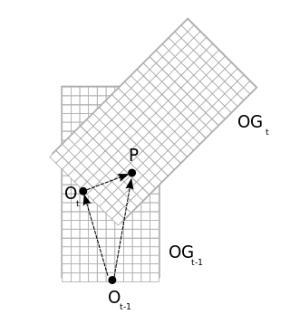
The objective of this module is to separate the input occupancy grid into two parts: cells belonging to static objects and cells belonging to moving objects. The main idea of this separation between static and dynamic parts, consists of keeping a track of how many times a cell is observed as free and how many times it is observed as moving. However to realize this concept we must solve the localization problem. We solve this problem using velocity and rotation information given by MTi-G XSens unit. This allows us to map cells between two input grids and at time and as shown in figure 7 .
|
We use two sets of and counter arrays. One set is initialized from new input grid at time whereas other set keeps updated counts until time . Then after above transformation betweens cells of grids and newly initialized set of arrays is updated from arrays at time , resulting in incremented counts for overlapping areas between two grids. Finally following decision function is used to separate cells of current input grid into static and dynamic parts and results are stored in a motion grid.
This technique being simple is quite robust and efficient and does not oblige us to solve the complete SLAM problem. This work is published as [19] and [20] .
Integration within the BOF framework
We have updated the BOF implementation to take into account the motion detection results. The motion grid is used as an input for updating the BOF. If the input motion grid tells that a cell belongs to a static object, then during prediction and update cycles of BOF the cell's velocity distribution over the velocity range is set to uniform for all discrete velocity values. This essentially means that no velocity information for a given cell is available and the cell is labeled as static in the current BOF implementation. However, if the cell has been detected as belonging to a moving object, then the velocity distribution prediction and the update cycle are carried out normally. In formal terms this change in the parametric form of dynamic model can be stated as:
where is the set of antecedents of cell at time and is a parameter of BOF, modelling the prediction error probability.
Integration with FCTA
We have also updated the FCTA implementation to take into account the motion detection results. The cells which do not possess the velocity information are now ignored during the clustering step. While generally most of the areas belong to static objects and are detected as static by the motion detection module, two main advantages are expected from this strategy: (i) the clustering stage of the algorithm is highly accelerated by the reduction of hypotheses, and (ii) the false moving clusters are ignored because they are not considered for clustering, even with the relaxed FCTA parameters.
Results
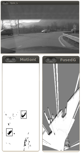
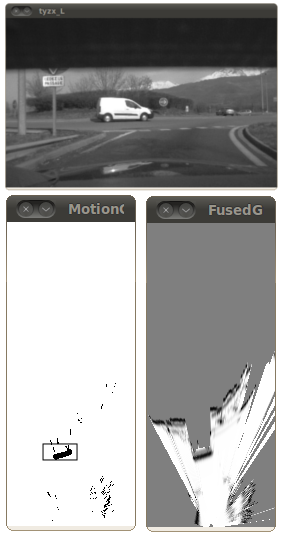
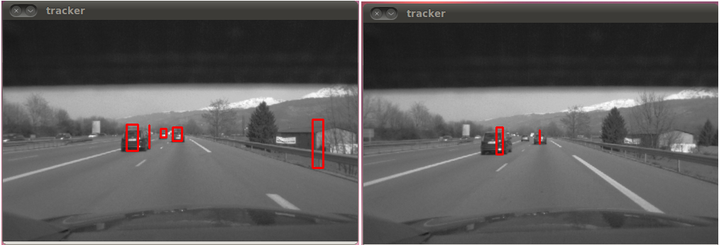
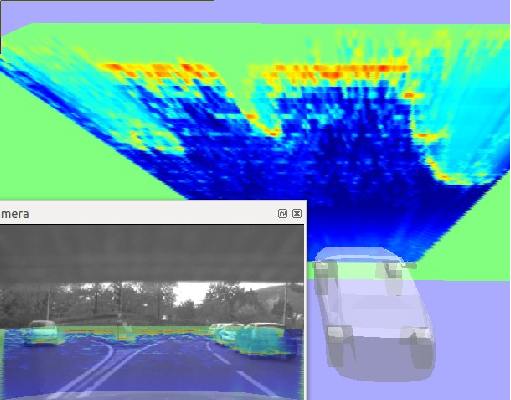
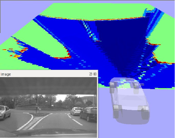
Some qualitative results of motion detection module are shown in figure 8 , (rectangles around the objects are drawn manually to highlight them). As expected, the moving objects are properly detected. For example, figure 8 (left) shows the motion detection scenario of two cars, and the car moving around a roundabout has been successfully detected in figure 8 (right). Some noise is also visible on the results, mainly due to two causes: first, the uncertainty on the IMU measurements along with the circular motion model may result in some errors in the estimation of the motion; second, the decision function is too rough for taking correct decisions in every situation. The results would benefit from replacing this function by a probabilistic model.
|
The tracking results of FCTA are highly sensitive to its parameters values. There are less false positives when strict parameters (large thresholds) are used, however, a large number of the true tracks may be missed, resulting in numerous miss detections -note that since the focus of this work is to detect moving objects, we consider in this part that detections belonging to the static environment are false alarms-. The relaxed parameters (small thresholds) provide less miss detections, however, a large number of false tracks are detected. While finding the appropriate set of parameters can be a challenging task, our implementation of the motion detection module with relaxed parameters represents a trade-off.
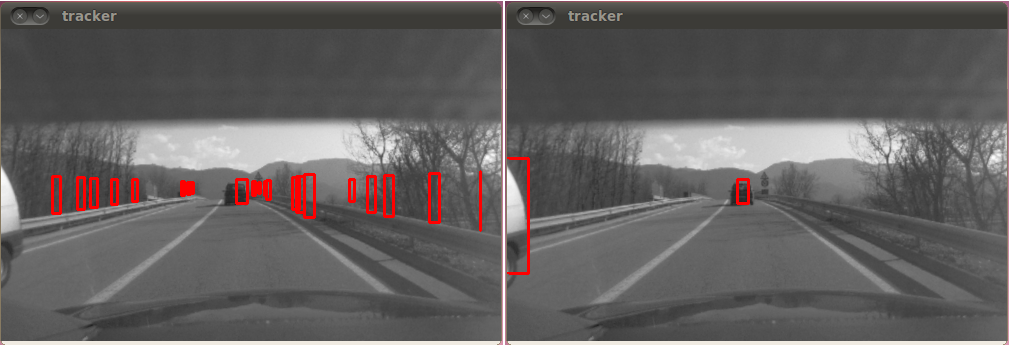
The following statistics with a dataset duration of about 13 minutes give an insight into the improvements gained with this implementation. When the motion detection module is not used, 22303 tracks are detected. The activation of the motion detection module with all other parameters being equal provides to detect 4796 tracks. This example shows the advantage of the motion detection module because it allows us to remove most of the false tracks while leaving most of the true tracks. Some qualitative FCTA tracking results with and without motion detection module activated (with all other parameters being same) are shown in figures 9 and 10 . Red rectangles are the detected tracks by FCTA in the shown scenario. We clearly see that most of the false positives have been removed.
|
|
Conclusion
In this section we have presented a fast technique to find moving objects from laser data and its integration with Bayesian Occupancy Filter (BOF) and Fast Clustering-Tracking Algorithm (FCTA). We have seen that after this integration we were able to remove a significant number of false alarms, this has also relaxed the dependence of results on the FCTA parameters.
We plan to change the rather ad hoc decision module that is currently based on occupied and free counter values to a more formal probabilistic function that also takes into account the uncertainty effects on the neighboring cells to accommodate the localization errors. We are also working on extending the tracking module from single motion mode to multiple motion modes.
Vision-based Lane Tracker
Participants : Mathias Perrollaz, Amaury Nègre.
For perception in road structured environment the detection of the lane markers and its localization provide an interesting information to predict drivers behaviors and to evaluate collision risks. We currently develop a real time road lane detection and tracking application using camera's image information. The tracking application estimates simultaneously the road plane orientation, the lane curvature and the camera position by using a Monte-Carlo particle filter. With this method, the parameter distribution is represented by a set of particles (see Fig 11 .a) that are sequentially updated using the vehicle dynamic model, evaluated by a ridge extraction (Fig 11 .b) and sampled considering the evaluation result. The average of the particles, displayed on Fig 11 .c) provides a good estimation of the lane state.
To obtain real-time performance, we implemented the whole process on GPU using the nVidia Cuda toolkit.
The output of this application has been mainly used to predict lane change behaviour 6.2.1 and to risk estimation applications.
|
Experimental platform for road perception
Participants : Nicolas Vignard, Mathias Perrollaz, Amaury Nègre.
Experimental platform material description
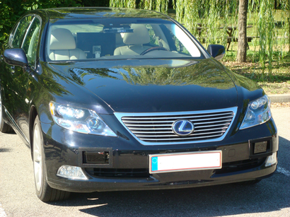
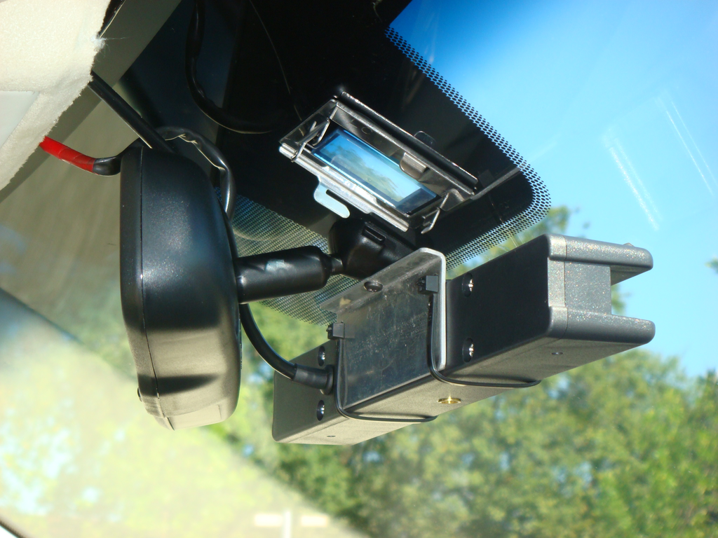
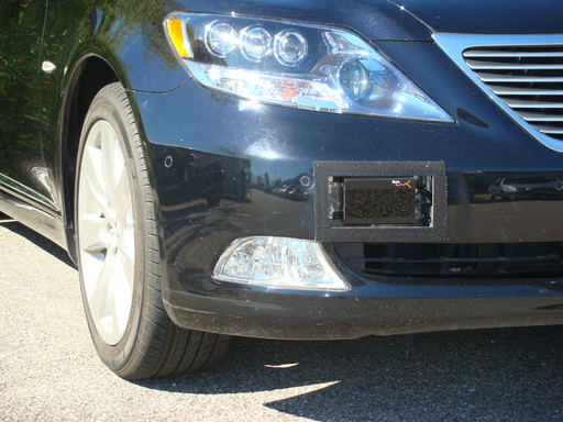
Our experimental platform is a Lexus LS600h car shown in Figure 12 . The vehicle is equipped with a variety of sensors including two IBEO Lux lidars placed toward the edges of the front bumper, a TYZX stereo camera situated behind the windshield, and an Xsens MTi-G inertial sensor with GPS.
|
The stereo camera baseline is 22 , with a field of view of . Camera resolution is 512x320 pixels with a focal length of 410 pixels. Each lidar provides four layers of up to 200 impacts with a sampling period of 20 . The angular range is 100, and the angular resolution is 0.5. The on-board computer is equipped with 8GB of RAM, an Intel Xeon 3.4 processor and an NVIDIA GeForce GTX 480 for GPU. IMU data contains accelerations, velocity, GPS position and steering angle. The experiments are conducted in various road environements (country roads, downtown and highway), at different time of the day, with various driving situations (light traffic, dense traffic, traffic jams). The datasets are acquired online and are used for testing of our sensor fusion and risk assessment algorithms.
Migration from Hugr to ROS middleware
Our platform described in 6.1.5.1 previously used a middleware named Hugr. Middlewares bring an abstraction layer between the sensors drivers and the processing modules. We also used this middleware to share information with modules and applications. Using a middleware facilitates and normalises the communication between modules.
Hugr has been developed by inria for the Cycab project and a team was built to add functionalities and maintain this new middleware. However, now the team has to work on other projects and it is becoming increasingly difficult to allocate resources to maintain this middleware. Given this and some other technical issues [49] , we have decided to change our robotic middlware.
We find that many different middleware (AROCAM, RTMaps, ROS,) are being used in the robotic community [53] . Among these, Robotic Operating System (ROS) is increasingly becoming a research standard in robotics. The reason being: an important community, a lot of tools and sharing work and development. The primary goal of ROS is to develop faster robotics applications. However, before moving to ROS we also did an extensive research on the comparison between Hugr and ROS [49] , that supported our this decision.
Because of this middleware change, we had to reimplement all the perception process from drivers to applications. In this regard, we have implemented the following drivers:
However for the Xsens MTi-G, we found an existing driver that we modified to add the GPS functionality http://www.ros.org/wiki/lse_xsens_mti .
Furthermore, we have also migrated the following modules:
Some result images of occupancy grids and data from the lane tracker after this migration to ROS are shown below 13 . Finally, we have created a public repository at http://gforge.inria.fr that share our developments (both drivers and modules).
|
Disparity space approach for a vision based occupancy grid
Participants : Mathias Perrollaz, Anne Spalanzani, John-David Yoder, Amaury Nègre, Christian Laugier.
To use sensors in the BOF framework, it is essential to develop an associated probabilistic sensor model that takes into consideration the uncertainty over measurements. In 2009, we proposed such a sensor model for stereo-vision [72] . The originality of the approach relied on the decision to work in the disparity space, instead of the classical Cartesian space. In 2010, we improved our sensor model, in order to mimic some features of the sensor models used for range finders. Particularily, we worked on managing visible/occluded areas of the scene [74] , and on including the information from the road/obstacle segmentation of the disparity image [73] . Our approach was also designed to allows highly parralel computation of the occupancy grid. A. Nègre implemented the approach on GPU using NVIDIA CUDA to enhance the performance. The complete processing of the stereo data can now be done in 6 ms, while more than 150 ms were necessary with the CPU implementation. The complete approach for occupancy grid computation using stereovision has been publish in 2012, in [13] .
Software and Hardware Integration for Embedded Bayesian Perception
Participants : Mathias Perrollaz, Christian Laugier, Qadeer Baig, Dizan Vasquez.
The objective of this recently started research work is to re-design in a highly parallel fashion our Bayesian Perception approach for dynamic environments (based on the BOF concept), in order to deeply integrate the software components into new multi-processor hardware boards. The goal is to miniaturize the software/hardware perception system (i.e., to reduce the size, the load, the energy consumption and the cost, while increasing the efficiency of the system).
This work has been started in 2012 in cooperation with CEA-LETI DACLE laboratory. During 2012, we have worked on the definition of the software/hardware architecture and we have started to re-think some components of the lower layer of the BOF software module.
The work plan has been split in two three-year-long phases, respectively leading to address a first level of integration based on mobile technologies, and a second level of integration, based on a more dedicated hardware architecture (and maybe to a SOC).
Two cooperative projects have been prepared and submitted this year for supporting this promising research: the “Permobile” project (FUI), involving industrial companies and user, and the “Perfect” project (IRT-Nano) involving the CEA-LET LIALP lab and ST-Microelectronics. Permobile is focusing on the first integration objectives (3 years) and has been recently submitted. Perfect is focusing onto the second integration objectives (6 years) and the development of integrated open platforms in the domain of transportation (vehicle and infrastructure) and in a second step in the domain of health sector (mobility of elderly and handicapped people, monitoring of elderly people at home…).