Section: Application Domains
Energy conversion
Fluid-structure interaction
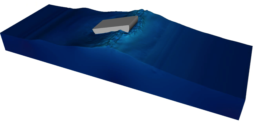
We apply the methods developed in our team to the domain of wind engineering and sea-wave converters. In Figure 1, we show results of a numerical model for a sea-wave energy converter. We here rely on a monolithic model to describe the interaction between the rigid floater, air and water; material properties such as densities, viscosities and rigidity vary across the domain. The appropriate boundary conditions are imposed at interfaces that arbitrarily cross the grid using adapted schemes built thanks to geometrical information computed via level set functions [46]. The background method for fluid-structure interface is the volume penalization method [27] where the level set functions is used to improve the degree of accuracy of the method [3] and also to follow the object. The underlined mathematical model is unsteady, and three dimensional; numerical simulations based on a grid with degrees of freedom are executed in parallel using 512 CPUs .
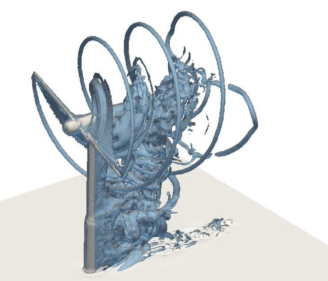
In the context of the Aerogust (Aeroelastic gust modelling) European project, together with Valorem, we investigated the behavior of wind turbine blades under gust loading. The aim of the project was to optimize the design of wind turbine blades to maximize the power extracted. A meteorological mast (Figure 2(a)) has been installed in March 2017 in Brittany to measure wind on-site: data provided by the mast have been exploited to initialize the mathematical model. Due to the large cost of the full-order mathematical model, we relied on a simplified model [38] to optimize the global twist. Then, we validated the optimal configuration using the full-order Cartesian model based on the NaSCar solver. Figure 2(b) shows the flow around the optimized optimized wind turbine rotor.
|

Schemes for turbulent flow simulations using Octrees
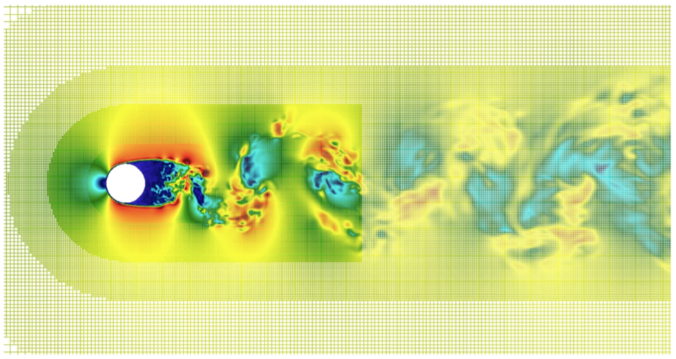
We have initially developed and tested a 3D first-order Octree code for unsteady incompressible Navier-Stokes equations for full windmill simulations with an LES model and wall laws. We have validated this code on Occigen for complex flows at increasing Reynolds numbers. This step implied identifying stable and feasible schemes compatible with the parallel linear Octree structure. The validation has been conducted with respect to the results of a fully Cartesian code (NaSCAR) that we run on Turing (with significantly more degrees of freedom) and with respect to experimental results.
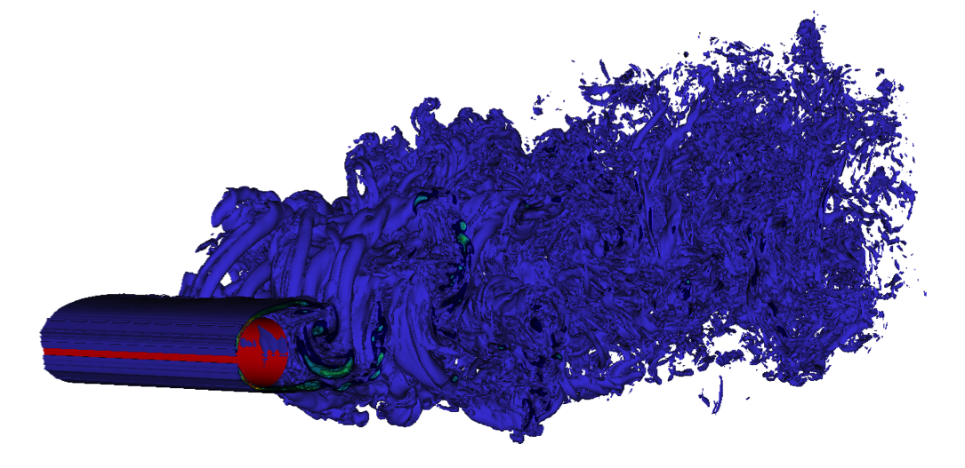
Subsequently, we have developed a second-order Octree scheme that has been validated on Occigen for a sphere at a moderate Reynolds number (), see Table 1. Then, for a cylinder at () (Figures 3(a) and 3(b)), close to real applications, we have preliminary validation results for the second-order scheme with respect to experimental drag coefficient (Table 2). Additional resources will be asked on Occigen to complete the study.
| Mesh | number of cells | (1st-order scheme) | (2nd-order scheme) | |
| 1 | N.A. | |||
| 2 | ||||
| 3 | ||||
| 4 |
| Case | |
| Octree, 1st-order scheme | |
| Octree, 2nd-order scheme | |
| Cartesian | |
| Experimental estimate [34] |