Section: New Results
Perception-adapted controller device for autonomous vehicles
Participants : Imane Mahtout, Fawzi Nashashibi.
Without loss of generality, let us consider a single camera for detecting a preceding vehicle in the road. It is clear that there are two parameters that impact the performance of the perception system:
1) the specific algorithm developed to detect and track the objects providing accurate measurement; and
2) the physical limitation of the sensor itself. For a camera, the number of pixels limits the resolution of the image so the farther away the vehicle is, the lower the accuracy in its detection. This implies a more inaccurate measurement that will degrade the ego-vehicle performance. From the vehicle response point of view, we cannot expect that a single control device can handle for example a camera-based car-following system for all detected vehicle distances.
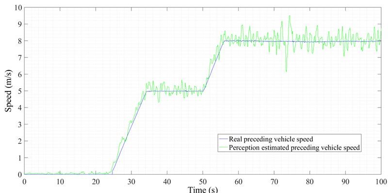
For the sake of clarity, Figure 2 shows the speed of a preceding vehicle measured from a ground truth (solid blue line); and the measured speed from an on-board perception system. The speed of the preceding vehicle was computer controlled so we can assure a given response for it. In this example, it follows four consecutive reference speed changes from 0 to 5m/s, and finally to 8m/s. The ego-vehicle equipped with the on-board perception system was following that preceding vehicle at a speed dependent distance (i.e. as any on-the-market ACC system), meaning than the higher the speed, the higher the inter-vehicle distance. One can clearly see how the higher the speed, the higher the inaccuracy of the perception system, the more degraded the measurement.
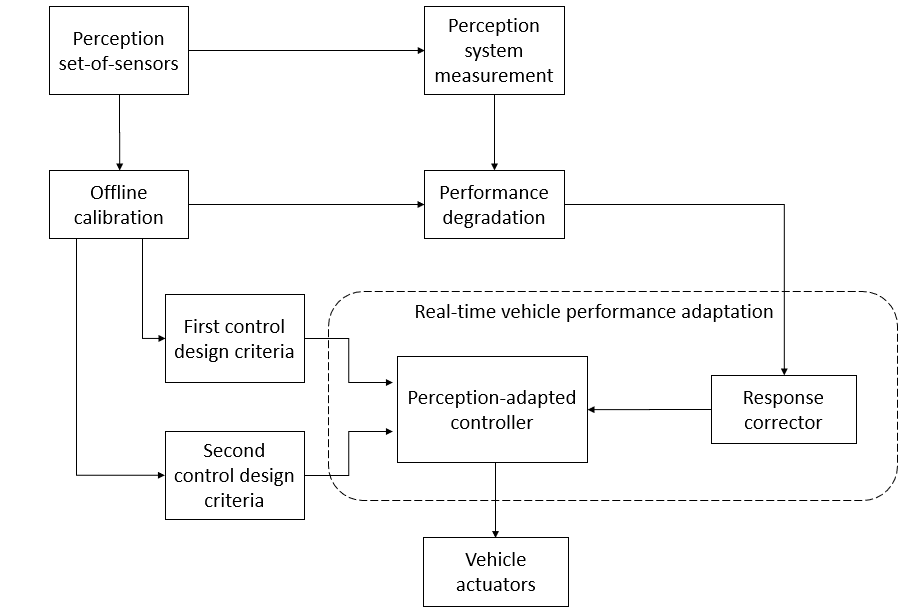
We worked on a novel control device able to adapt its response to the perception system capabilities, modifying vehicle response accordingly to the level of accuracy of the perception system. This novel idea redefines and extends the capabilities of any ADAS or autonomous vehicle technology, not only because it improves vehicle’s performance but also because we can, a-priori, understand the limitations of the full vehicle performance with a complete closed loop analysis from perception to vehicle control. As additional remark, there are ways of dealing with these problems by filtering the perception signal. This causes two problems: control response stability is no longer guaranteed, and it smooths the response but it’s not possible to link the full system performance to that filtering. Figure 3 presents an overview of the method. The block Perception set-of-sensor represents the specific embedded perception system. It can consist either in a single sensor or a combination of them. The characterization of the specific perception setup can be done offline, calibrating the system performance accordingly to the on-board sensors. The module Offline calibration will contain a 3-D look-up table with object distance, preceding-vehicle speed, and as a third parameter the desired measurement inaccuracy (it can be either the speed as shown in Figure 2 or any other relevant parameter as the distance, yaw rate…). This offline calibration allows defining specific design parameters for the vehicle performance. Current control systems linked to perception don’t consider this inaccuracy when designing the vehicle performance. We here include two different control design criteria blocks. Assuming that we keep the regular controller design that considers perfect measurement from the perception system; the First control design criteria block includes the current production system controller. On the contrary side, we have also included a Second control design criteria block that can be adapted in function of the specific interest of each application. Following with the example on Figure 2, let us assume that we are interested on developing an application between 0 and 10m/s and the inaccuracy of the perception system is the one presented in the plots. Having this in mind, we can design the second controller with the goal of minimizing the impact of that inaccuracy in the vehicle performance. The system also uses as input the real-time perception value coming from the Perception system measurement block (in the case of Figure 2 would provide the speed of the preceding vehicle in real-time). Then, this measurement feds the Perception-adapted controller block and the Performance degradation block. This last, accordingly to the information from the Offline calibration block, determines the status of the on-board perception system. The output of the Performance degradation block with the output of the first and second design criteria blocks fed the core module of this work: the real-time vehicle performance adaptation module. It is composed by two main blocks: the response corrector block to adapt the vehicle performance and the Perception-adapted controller block that merges both designed controller in a single stable structure.