

Section: New Results
Neuroprostheses
Stimulator calibration
Participants : Jérémie Salles, Fabien Soulier, Serge Bernard, Guy Cathébras.
In the context of the time project, one cafe12 -based stimulator will be used for chronic experiment in human. During the validation of the stimulator, it appeared that we needed to improve both the linearity and the current matching of the 12 channels. We thus define a calibration process consisting in:
-
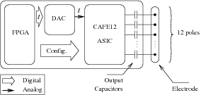
PCB modification: To take advantage of the 10 bits of the DAC (only 8 were used before for compatibility reasons). The modification give the FPGA access to the two latter bits. Moreover, test points were added between the asic and the output capacitors that now can be removed for the calibration phase.
-
Digital interface modification: To allow a 16th current amplifying ratio (only 0-15 were enable). Improvements in the activation sequences of output current mirrors have also been carried on.
-
Reference voltage and current tuning: The stimulator use several level of power supply and voltage references. Nominal values are:
The dac current reference is set to get a maximum current at the stimulator output for ratio of 15. We have enabled modification of the biasing resistor in order to fine-tune this current reference.
-
Raw data acquisition: Measurement of the 12 output currents are carried on independently with the following configuration:
The measurement setup makes use of a characteristic analyzer (HP4156A) to maintain the voltage load to for all the dac current values.
-
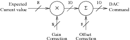
Correction: The linearity and matching correction is specific to the association of a particular asic with a particular dac . For human experiment, the configuration will be limited to common anode/controlled cathodes. A first-order linear regression is applied to the 12 raw current measurements. This gives gain and offset adjustments for each channel that are applied by a linear digital correction block (fig. 14 ). The dac initial value (8-bit) is multiplied by the correction gain and summed to the correction offset (both channel-dependant), resulting in a 10-bit corrected command. At last, respective correction values are chosen and quantified to lower impact of these modifications to the precision and dynamic range of the stimulator output (no “lost” bit). Concerning the implementation, since the 3 most significant bits of the correction gain appear to be constant, it is possible to use channel-independent bit-shifts and a substractor to perform the 8 to 10-bit multiplication.
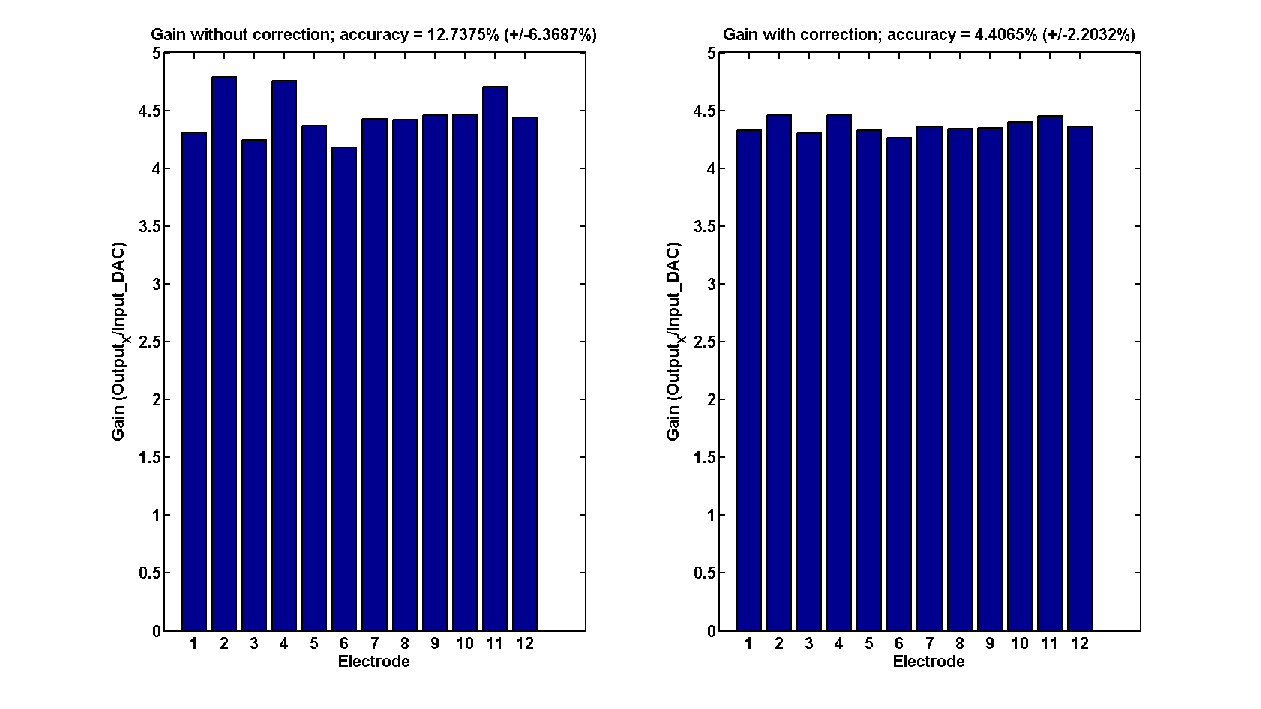
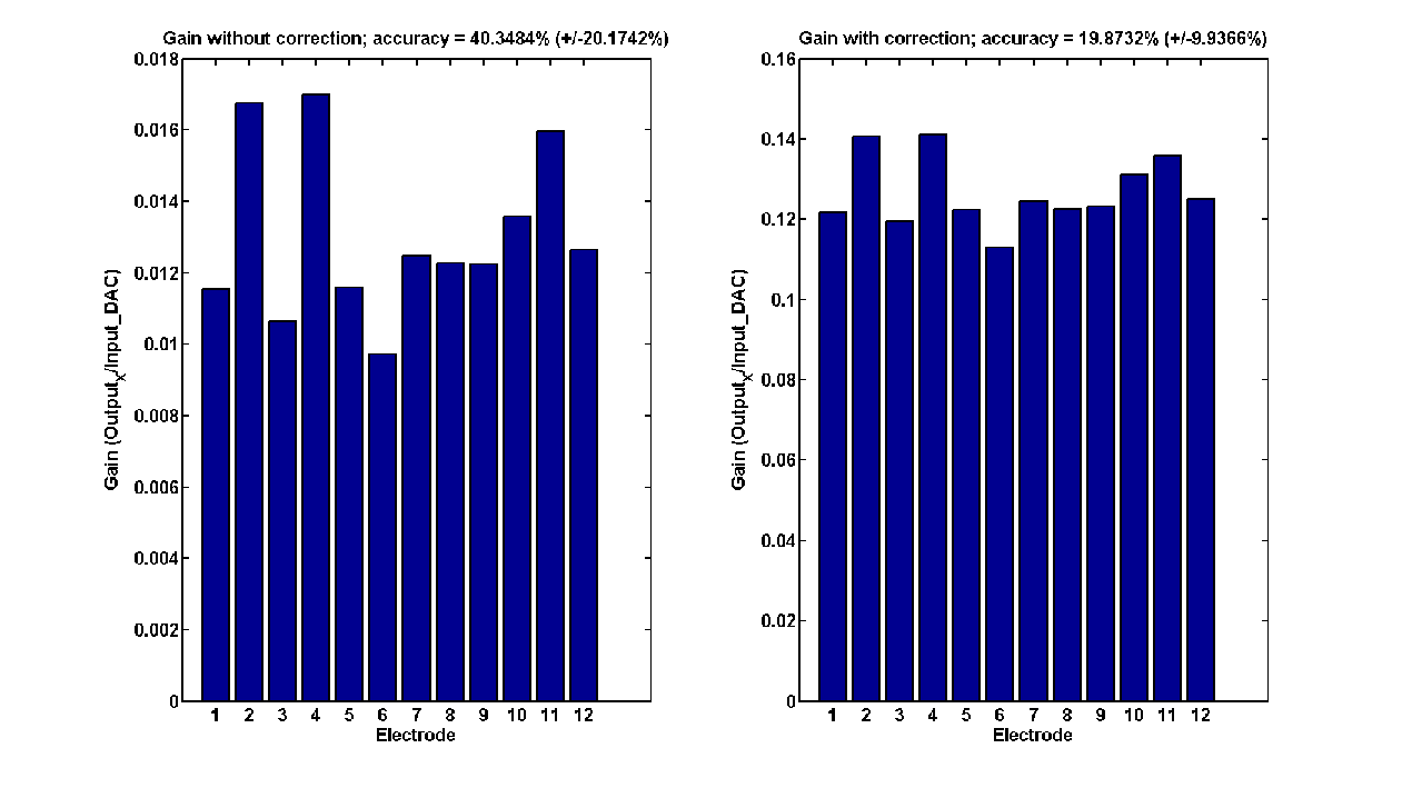
The improvement in the matching of the 12 channels can be seen in figure 15 . The results in terms of linearity are an integral non-linearity of and a differential non-linearity of .
Nerve Modelling for ENG recording
Participants : Olivier Rossel, Jonathan Coulombe, Fabien Soulier, Serge Bernard, Guy Cathébras.
In the context of fes , neural recording is one of the main issues, as the control requires information carried on afferent peripheral nerves. Because specific information are carried in different fascicles, we propose to realize a non-invasive and spatial-selective electrode. Last year, based on investigation on the topic of extracellular Action Potentials (ap) , we proposed a new tripole design, where the tripolar output signal is the image of the activity in the close vicinity of this tripole, providing high spatial selectivity.
We showed however, that this high spatial selectivity is achieved at the expense of signal amplitude. This first result jeopardizes the feasibility of this kind of electrode since the signal amplitude appears to be on the same range of the expected noise. First, we propose to estimate the performance of the proposed electrode with a quantitative study of the electrode selectivity. Then, to conclude on the feasibility of this electrode, the snr has to be determined. So with a more accurate model, we studied the sensitivity of the proposed tripole, allowing to determine precisely the amplitude level of the expected signal. Thus, the snr can be estimated knowing the expected noise.
In short, the work of this year aims at characterizing the performances and evaluating the feasibility this new multi-contact cuff electrode.
Selectivity
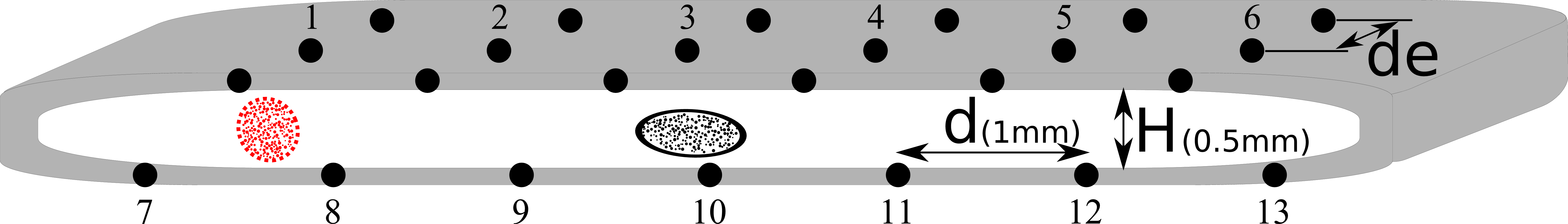
We proposed an electrode configuration inspired from the FINE electrode (figure 16 ) designed for the same purpose. The electrode is composed of many tripoles, placed around the nerve. This disposition is used for two electrode, state-of-the-art electrode a and the proposed electrode b . The unique difference between both electrode resides on the longitudinal inter-pole distance (), which is respectively for the electrode a and for the electrode b .
|
The electrodes performances are evaluated based on simulations using a model of a nerve comprising multiple fascicles [38] . The Selectivity Index (si ) quantifies the ability to record and distinguish between different active fascicles in such a manner that corresponds to a case where an active fascicle yields identical signals at every recording site, while occurs when one recorded signal is different from every other. This si has to be presented according to the inter-fiber spacing.
|
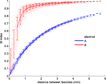
The result of electrode selectivity are presented in the fig. 17 . This figure shows that activity of two fascicles separated by as little as can be distinguished for the proposed electrode (for this distance si for electrode b ( 0.9) is more than double that of electrode a (). The proposed electrode thus appears to be much more selective than the reference electrode.
Sensitivity
Using a more realistic model (inhomogeneous and anisotropic), we investigate the spatial properties of extracellular ap and that of the filtering done by the proposed tripole [37] . This allows us to represent the tripolar sensitivity. It was realized for the proposed tripole b and compared to a state-of-the-art tripole a 18 . This sensitivity represents the amplitude of the tripolar output signal for a single unit action potential.
|
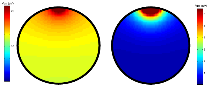
This figure shows that the classical tripole radial sensitivity is huge compared to that of the proposed electrode. This confirms the high spatial sensibility of the proposed tripole. We can also determine the expected amplitude, where the signal can reach . Considering this amplitude and knowing that in natural case there will be superposition of action potentials, we can conclude that the signal amplitude could be higher than the expected noise (around ). So we can conclude positively to the feasibility of this kind of electrode.
Low-noise, low-power ENG amplifier design
Participants : Jonathan Coulombe, Olivier Rossel, Fabien Soulier, Serge Bernard, Guy Cathébras.
This year we proposed a method for enhancing the noise-power tradeoff of front-end amplifiers in parallel recording applications of analog signals with respect to a common reference. One example of application is shown in the Fig. 19 for spatial-selectivity eng recordings.
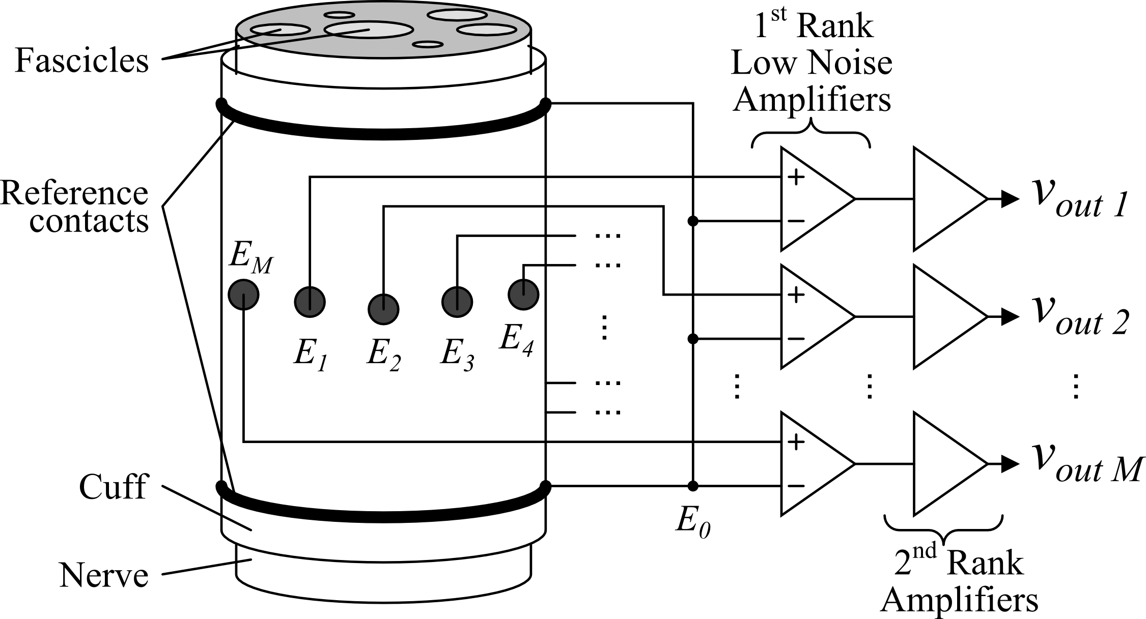
The circuit architecture is based on a Shared-Input Amplifier (sia ), composed by shared-input transconductance amplifiers and a differential stage. Averaging null signals and subtracting the result from every signal reduce the noise because the correlated noise between parallel outputs is attenuated. It results significant supply current savings without noise penalty. One example is shown in the Fig. 20 for the specific case of two average of two null signals.
|
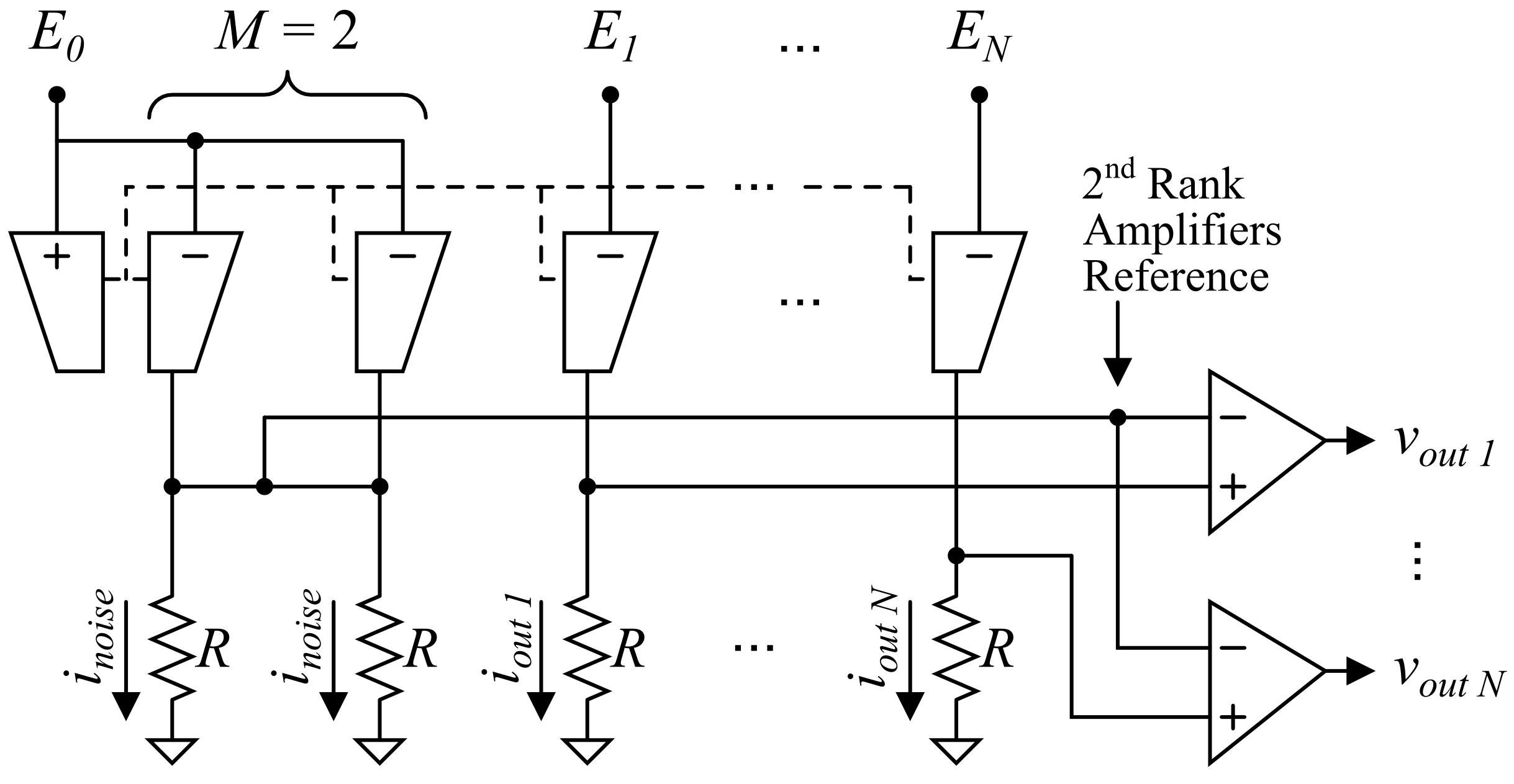
Also, a method for reducing the remaining noise with little power penalty is possible. And it is possible to combine both methods, either noise level, total supply current, or both can be significantly reduced. The benefits of combining both methods and the related trade-offs was validated by simulations using models of a BiCMOS process. So we have shown that the total supply current can be reduced by more than that of a comparable system using conventional differential amplifiers with equivalent output noise. Alternatively, the noise can be reduced by approximately with comparable power consumption.
This should enable low-noise recording of signals with significantly better efficiency than even the theoretical limit of any conventional differential amplifier. Future work will include circuit optimization and investigation of the impact of the architecture over other performances of the system, such as crosstalk, linearity, distortion, and channel mismatch. Implementation of the circuit for full characterization is expected to be completed in the near future.