Section: Software
Software Platforms
JBox2D wrapper
Participant : Fabien BENUREAU [correspondant] .
ProcBox2D is a wrapping of Processing and JBox2D to satisfy common robotic research needs. In order to quickly prototype research ideas, a simple and efficient simulation framework is of great use. JBox2D is a 2D rigid-body physic engine. Written in Java, it is very fast, typically allowing to compute simulation 60 times faster than real time. Mass simulations can be carried in a timely manner, and improving the process of iterating the conception and implementation of new algorithms. Processing is a graphical framework in Java, and is used to display the simulations of JBox2D. An example of a simulation rendering is visible in Figure 3 .
|
While several libraries exist that expose the JBox2D engine to the Processing framework, they suffer from binding Processing irrevocably into the experiment description. As such, simulations without a graphical context, a situation commonly encountered on remote servers and computing clusters are impossible using these libraries. ProcBox2D was written to fill this gap. It allows the conception of experiments to be done using Processing display capability, while, later one, without modifications of the code, to execute the simulations without any dependency to Processing, on a cluster for instance. The use of Processing allows interactions with the scene via the mouse, which makes ProcBox2D a potential tool in demonstration or imitation learning experiments.
ProcBox2D also provides a sensor and controller interface. Actuated joints can be controlled in torque and velocity, and a PID controller for position control is planned. ProcBox2D implementation begun in November 2011 and was presented and made available to the team in December 2011. It is expected that it will increase productivity of researchers that previously had to work out a solution for themselves, often using in early stage of research complex and time-consuming simulation frameworks.
V-REPBridge
Participant : Paul FUDAL [correspondant] .
V-REPBridge (formally uV-REPBridge) is a set of software tools to control V-REP through an external client; it consists of a plugin for V-REP and an API to control V-REP.
V-REP - the Virtual Robot Experimentation Platform - is a robot simulator which allows the editing and simulation of robotic systems and sub-systems. Also, it can be integrated and combined using a complete API.
V-REPBridge is a way to interact with a simulation loaded through an Urbi script or a Python application. Based on network communication, V-REPBridge can be used locally (V-REP and the client on the same computer) or remotely. The V-REP simulator's main use is to perform experiments with virtual robots and environments. But, because V-REPBridge API provides classic functionality like, for example, setting position of a joint or its torque, getting sensor value, etc... an existing application built on top of V-REPBridge can be easily repurposed to use the interface of a real robots.
The development of the plugin for V-REP is made under Windows environment using the V-REP and Windows API. The plugin acts as a server to which a client can connect in order to control the simulation. The client is provided as an API written in C++. This API is available for Windows, Mac and Linux and bindings are available for UrbiScript and Python. The bindings are based on the Urbi API and the Boost Python Library.
Today, V-REPBridge is fully functional and already used in several research experiments, and provide more than 130 V-REP API functions which can be called by the client; here is an non-exhaustive list of V-REP functionalities available in the client :
-
joint functionality (position, velocity, torque, etc...),
-
object functionality (position, orientation, etc...),
-
force sensor functionality,
-
inverse kinematic and geometric functionality,
-
proximity sensors functionality,
-
collision detection functionality,
-
minimum distance calculation functionality,
-
path planning functionality,
-
dynamic functionality,
-
...
V-REPBridge is also provided with an user documentation which includes some howtos (build, use), a complete list of available functions (with synopsis and parameters/returned value description) and some short examples written in Urbi and Python.
Finally, a developer documentation will be available soon to help developers who wants to implement missing V-REP calls both in the plugin and the client, or wants to implements theirs owns functions callable in the client.
The development of V-REPBridge was started at the beginning of year 2011. First release was made in February for testing and debugging foundation of the software. After this short period, time was spent expanding the software and adding new functionalities to bring a response to the needs of the team. First experiments with V-REPBridge was made for IJCAI in july (Mai NGUYEN), ICDL in august (Mai NGUYEN/Matthieu LAPEYRE) and Humanoid in october 2011 (Matthieu LAPEYRE). It was a good feedback for improving the performance and to identify potential improvements.
Work is still in progress for minor bugfixes, support of V-REP minor releases and preparation of the future version of V-REP which will run not only Windows but also on Linux and Mac OS X. A first private beta of V-REP 3 will be available at the end of january.
Rhoban Move Studio
Participants : Olivier Ly [correspondant] , Hugo Gimbert, Jérôme Béchu, Paul Fudal.
Main software stack
RhobanMoveStudio is a software suite to easily create and control robots, Acroban, FLOWERS Fields/Robot Lamps and Ergorobots/FLOWERS Fields in particular.
This platform has already been presented last year, but it has evolved, in particular for the motor control part. The software architecture has been kept similar but performance has been improved.
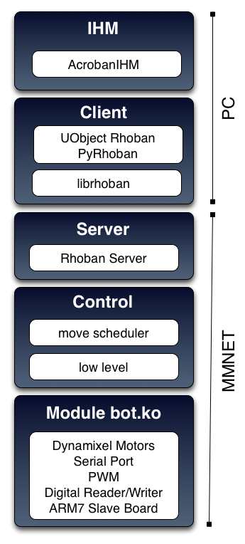
The system runs on an electronic board (based on ARM9 processor) and uses a linux distribution (OpenWrt). The sofware is composed of several layers :
-
Kernel module The role of the module is to implement the electronic communication with devices. It enables to manage Dynamixel (Broadly used servo motor product from Robotis http://www.robotis.com ) motors, generates PWM (Electronic signal : Pulse With Modulation) signals, uses digital readers/writers, I2C bus and more. This year the motor communication have been significantly improved and gained support fort accelerometers. This module is designed to run in root mode, to garantee execution without system interuption, as required by robotic application.
-
Low level This set of functions is used to communicate with the module through a dedicated shared memory.
-
Move Scheduler This library provides enables a high level specification of low level motor control loop based on graph of input/output blocks (see Section 5.3.3.2 ).
-
Rhoban server This software offers access to the full API of rhoban features through a TCP Socket.
-
Librhoban This TCP client library provides communication with the Rhoban Server and thus to the whole API. It is a dynamic library, thread safe and secure.
Except for the kernel module which is written in C ANSI, this softwares are written in C++.
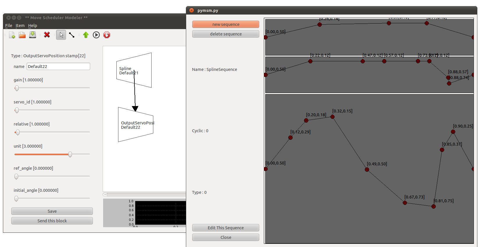
Move Scheduler
Recently (October 2011) a new layer was added to the software. Its role is to enable low level motor control loops through a high level representation.
This representation introduces the concept of blocks. Each block is a computing unit with inputs and outputs. The output of a block can be the input of another one, thus forming a graph of interaction between those unit. Each block is a function (for example addition, multiplication, derivation, integration, spline generation). Special blocks are also provided for sensor inputs and motor outputs.
Graphical interface was developped to easily designed such movements. it is called Move Scheduler Modeler, and written in Python (PyQt). This software has import/export capabilities to XML files.
UFlow
Participant : Jérome Béchu [correspondant] .
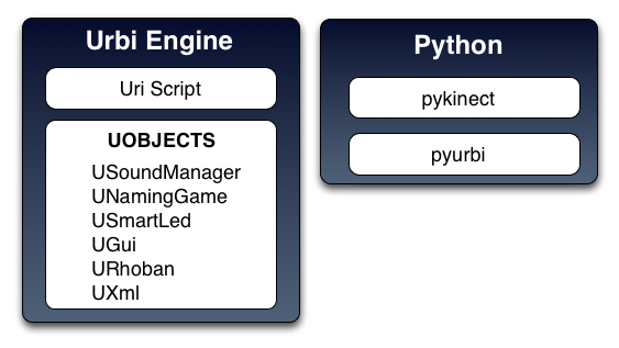
We developed some new UObjects to enrich the UFlow Toolbox. The UFlow Toolbox is a collection of various software modules for programming and scripting robot sensorimotor loops, aimed at allowing rapid prototyping in the FLOWERS team, and integrated in the URBI framework. URBI, developed by GOSTAI, supports the integration of heterogeneous robotic software modules. It uses a dynamic scripting language, which manages parallel and event processing. Each module, called UObject, is written in C++. We still continue to develop this collection of UObjects for the team.
USoundManager
This UObject is used to play sound. It's possible to update the sound while playing. This new version is already based on FMOD.
A new version has just been made. Based on OpenAL, this UObject has the exact same interface as the previous one expect that we include a media manager. With this functionality we load just one time the same sound (We keep it in memory a dictionnary of sounds).
URhoban
wrap the API of the librhoban (see the previous chapter). This tool is especially develop to control Bioloid motors in high frequency. With that software we can create instance of motors scanned and directly read and write features like position, torque, load, speed.
UXml
is an UObject based on TinyXml. It is designed to quickly save and restore URBI List in a xml file. It is generally used to store/load paramaters like the list of motors in the ErgoRobot platform.
USmartLed
was created to use the LinkM USB Device to control RGB lights. It is based on the linkm driver (modified to support multiple USB devices). We can control intensity of each light for each primary color.
UGui
is designed to draw basic 2D primitives. A new version based on SFML was developed this year. It is used in the ErgoRobot project to run a simulation of the setup with a graphical interface.
USqlite
is an UObject to wrap functionalities of SQLite in URBI. SQLite is a software library that implements a tiny SQL database engine.
UNamingGame
is UObject used to play the Naming Game. The Naming Game is an algorithm based on communication between agents, who progressively agree meanings of words.
ErgoRobot/Flowers Field Software
Participants : Jérôme Béchu [correspondant] , Pierre-Yves Oudeyer, Pierre Rouanet, Olivier Mangin, Fabien Benureau, Mathhieu Lapeyre.
In the context of its participation to the exhibition “Mathematics: A Beautiful Elsewhere” at Fondation Cartier pour l'Art Contemporain in Paris, starting from 19th October 2011 and to be held until 18th March 2012, the team has elaborated and experimented a robotic experimental set-up called “Ergo-Robots/FLOWERS Fields”. This set-up is not only a way to share our scientific research on curiosity-driven learning, human-robot interaction and language acquisition with the general public, but, as described in the Results and Highlights section, attacks a very important technological challenge impacting the science of developmental robotics: How to design a robot learning experiment that can run continuously and autonomously for several months?
The global scenario for the robots in the installation/experiment is the following. In a big egg that has just opened, a tribe of young robotic creatures evolves and explores its environment, wreathed by a large zero that symbolizes the origin. Beyond their innate capabilities, they are outfitted with mechanisms that allow them to learn new skills and invent their own language. Endowed with artificial curiosity, they explore objects around them, as well as the effect their vocalizations produce on humans. Human, also curious to see what these creatures can do, react with their own gestures, creating a loop of interaction which progressively self-organizes into a new communication system established between man and ergo-robots.
We now outline the main elements of the software architectures underlying this experimental setup.
System components
The software architecture is organized to control the experiment at several levels, and in particular:
-
Scenes: The organization of behavioural scenes, managing the behaviours that are allowed to each robot at particular times and in particular contexts;
-
Behaviours: The individual behaviours of robots, also called stems, which are outlined in the next section;
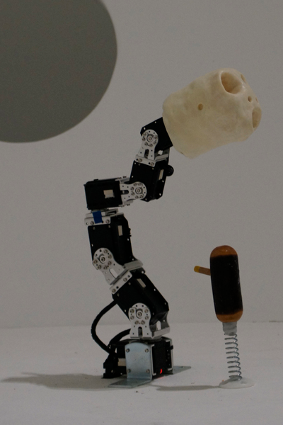
-
stems: The low-level actions and perceptin of robots while executing their behaviours, including motors control on the five physical stems, color and intensity of lights inside the stem head, production of sounds through speakers. Sensors are the kinect used to interact with visitors, and motor feedback capabilities.
In addition to that a video projector is used to display some artistic view of stem agents internal state.
Behaviours
A number of innate behaviours were designed and are used by the robots as elementary behaviours of more complex behaviours, including the three following learning behaviours.
The Naming Game is a behaviour played by stems two-by-two and based on computational models of how communities of language users can self-organize shared lexicons. In the naming game, stems interact with each other in a stylised interaction. Repeated interactions lead to the development of a common repertoire of words for naming objects. More precisely, object belong to meaning spaces. Two such spaces have been implemented for the exhibition. The first one is related to object spatial categorization and the second one is related to movement categorization. The object space contains stems, some hole in walls and the interaction zone. The movement space contains representations of small dances that stem can produce and reproduce.
Object Curiosity is a behaviour in controlling intrinsically motivated exploration of the physical environnement by the stems. A small wood object is present in the reachable physical environement of the stem, attached on the top of a spring so that it is guaranteed that it comes back to its original position. The stem uses a motor primitive to act on the object and motor feedback to detect movements of the object. The robot learns through active exploration what kind of parameters motor primitive will result in touching the object.
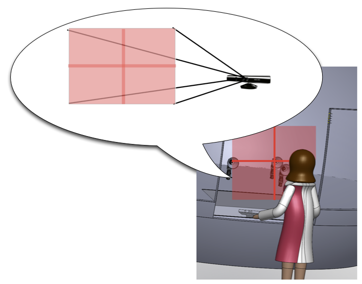
Birds Curiosity is a behaviour that drives robots to explore, through curiosity-driven learning, interaction with humans. One stem, generally the stem in the center, plays a sound, predicts the visitor reaction, look the interaction zone and wait the gesture of the visitor. To produce a sound the visitor have to make a gesture in space. In the next iterations, the robot chooses to produce sounds to human which produce most surprising responses from the human (i.e. the robot is “interested” to explore sound interactions which are not easily predictable by itself).. As describe in the picture, the space is split in four. Each zone corresponding with a sound.
Programming tools
The system is based on URBI and used some UObjects from UFlow. The most important part of the system is written in URBI script. Python and freenect (Kinect library) are used too.
The system at the startup detects motors and lights. It create dynamically a list of Stem. A Stem is one robot with 6 motors as described in hardware part.
To interact with people, we used the freenect library to interface with the kinect, with a binding to python where detection and following of gestures is made.
For the display, we display an abstract rendering of the structure inside each ErgoRobot, using a python parser to read and parse log file from the ErgoRobot system, and the Bloom/Processing software to create and display the rendering. Currently, the system has three displays, one for the naming game, another one for birds curiosity and the last one for objects curiosity.
The sound system used the UObject USoundManager. It plays sounds when required by a behaviour, it also plays word sounds in Naming Game behaviour.
The Light system used Linkm technologies. In the head of each ErgoRobot we put two lights devices. Each light device is a RGB Light. We can control the intensity of each primary color through I2C control. To control lights we used LinkM USB Device. And finally we used an UObject dedicated to communicate with the USB Device.
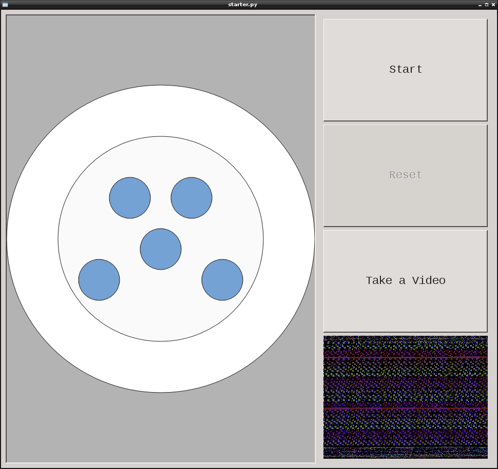
Maintenance
A dedicate maintenance software is used to switch off, switch on the system. This software is written in Python (and Qt). The status of ErgoRobots is display on the graphical interface. Buttons are present too : Start, Stop, Reset and Take a video.
Recently we added a video system to have a visual feedback of motors usage and also to detect eventual problems. This is a screenshot of the application :