Section: New Software and Platforms
Experimental Setups
Experimental Platform for User Study of Curiosity-driven Exploration
Participants : Pierre Rouanet [correspondant] , Jonathan Grizou, Brice Miard, Julie Golliot.
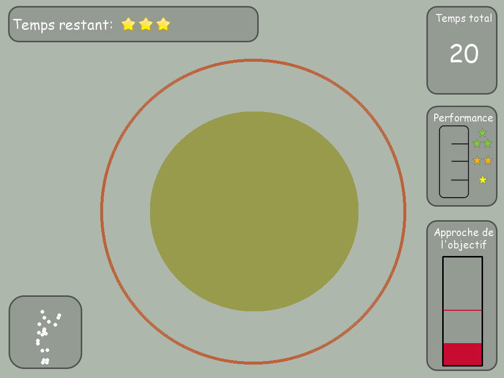
This platform has been developed to investigate curiosity-driven behaviors and more precisely how humans explore new sensori-motor spaces. It consists in several simple games where users control a 2D/3D shape with the movements of their body. They have to discover the mapping between their movements and a shape displayed on the screen and learn how to make the controlled shape match the target one (fig 10 ).
The software is entirelly written in Python. It includes a Kinect wrapper allowing the access of 3D position of tracked skeleton joints. It provides a framework for creating new games based on the 2D drawing library (pygame). It also includes a web server used to display game instructions, cut-scene videos and questionnaire.
The presentation of the platform and the preliminary results of a user's study have been rapported in [58] .
Learning and representing object assembly tasks
Participants : Yoan Mollard [correspondant] , Thibaut Munzer, Pierre Rouanet, Manuel Lopes.
In the context of the 3rd hand project 8.3.1.1 we created a framework for learning assembly tasks from demonstration. In this work we showed how a complex assembly task could be automatically decomposed in components allowing to learn constraints between different objects and their assembly plan. We created also a Graphical User Interface (GUI) allowing to present the learned data in a intuitive way, so that the user can be aware of what the computer has learned. This awareness is crucial for Human-Robot cooperation since the robot will base its decisions on the learned data. Making them clear to the user also allow to rely on him to find potential errors and correct the noise. Thus, the user can program the robot by combining demonstrations and manual corrections minimizing the overall programming phase. Our experimental setup consists in several sequencial phases:
-
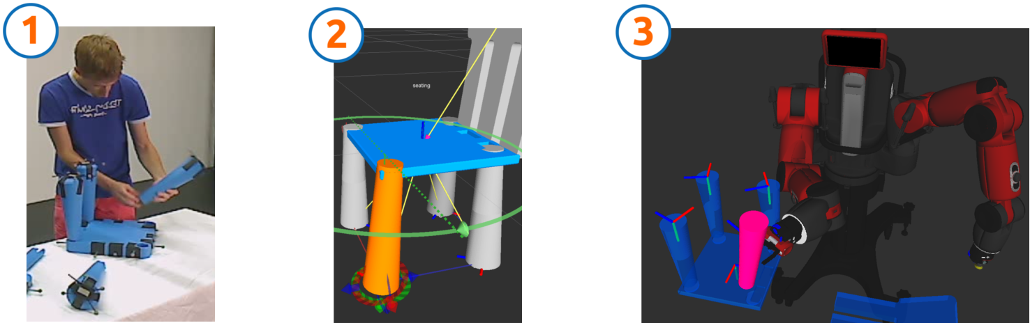
Demonstrations: User provides several demonstrations of an assembly. All parts of the objects are individually tracked by an Optitrack tracking system
-
Constraint extraction: Trajectories are analysed to extract rigid constraints
-
Segmentation: Constraints on all demonstrations are segmented to find one constraint per object
-
Plan computation: We deduce relational MDP trajectories from raw data, creating one assembly step per constraint
-
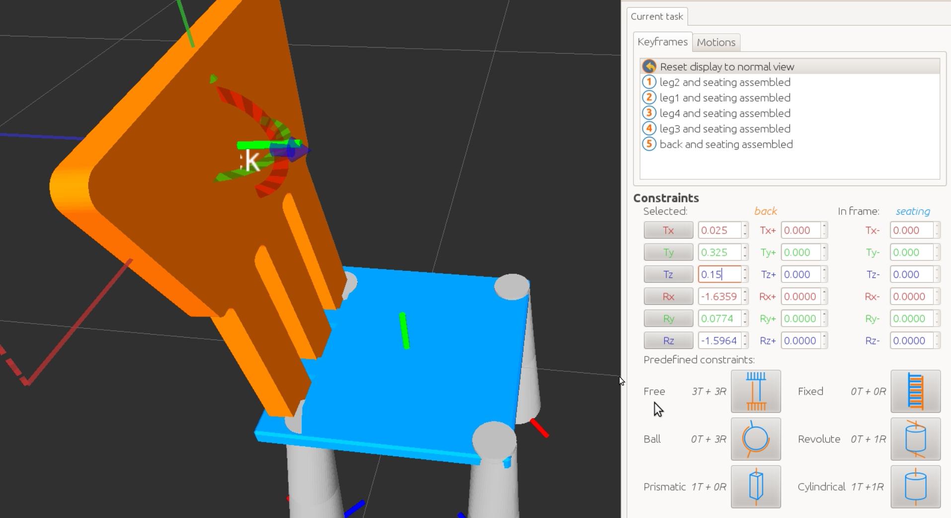
Presentation and correction: The raw constraints and assembly plan are presented to the user in a friendly way through a 3D GUI so that he is able to visualize and correct them 12
-
Execution: The corrected informations are then sent to the robot for actual execution. The execution system only receives constraints and the plan, all motions are computed by a motion planner to reach the goals, but motions could also been extracted from the demonstrations using dynamic motor primitives (DMP). We used a simulated Baxter robot that we acquired during the year.
The framework is written in C++ (GUI) and Python (tracking system, data analysis and execution system), and is completely integrated into ROS. The main steps of the workflow are shown on figure 11 .
The GUI itself 12 represents rigid constraints visually, and provides all the controls necessary to correct them using a graphical procedure. It shows the learned assembly plan as a list of sequential steps that the user can browse like any assembly manual. Also the GUI introduces degrees of freedom in the form of standard mechanical joints (rotational, prismatic, cylindrical joints ...) that the robot can use during execution to simplify the motions and decrease failures during motion planning. The GUI draw graphical cues to represent them and is also able to animate them to make them even clearer.